A few years ago I was asked to build an escape room van for the Melbourne University French language department, this was just as the world was about to go fully retarded and into COVID mode, so for most of the fuckery I was designing and building puzzles.
The purpose of the escape room was simple, it had to introduce high school aged children to the French language in a way where they might consider studying it further at university. The van would visit schools that already had French in their language curriculum so that students might already have French comprehension skills, or be able to study it if it appealed.
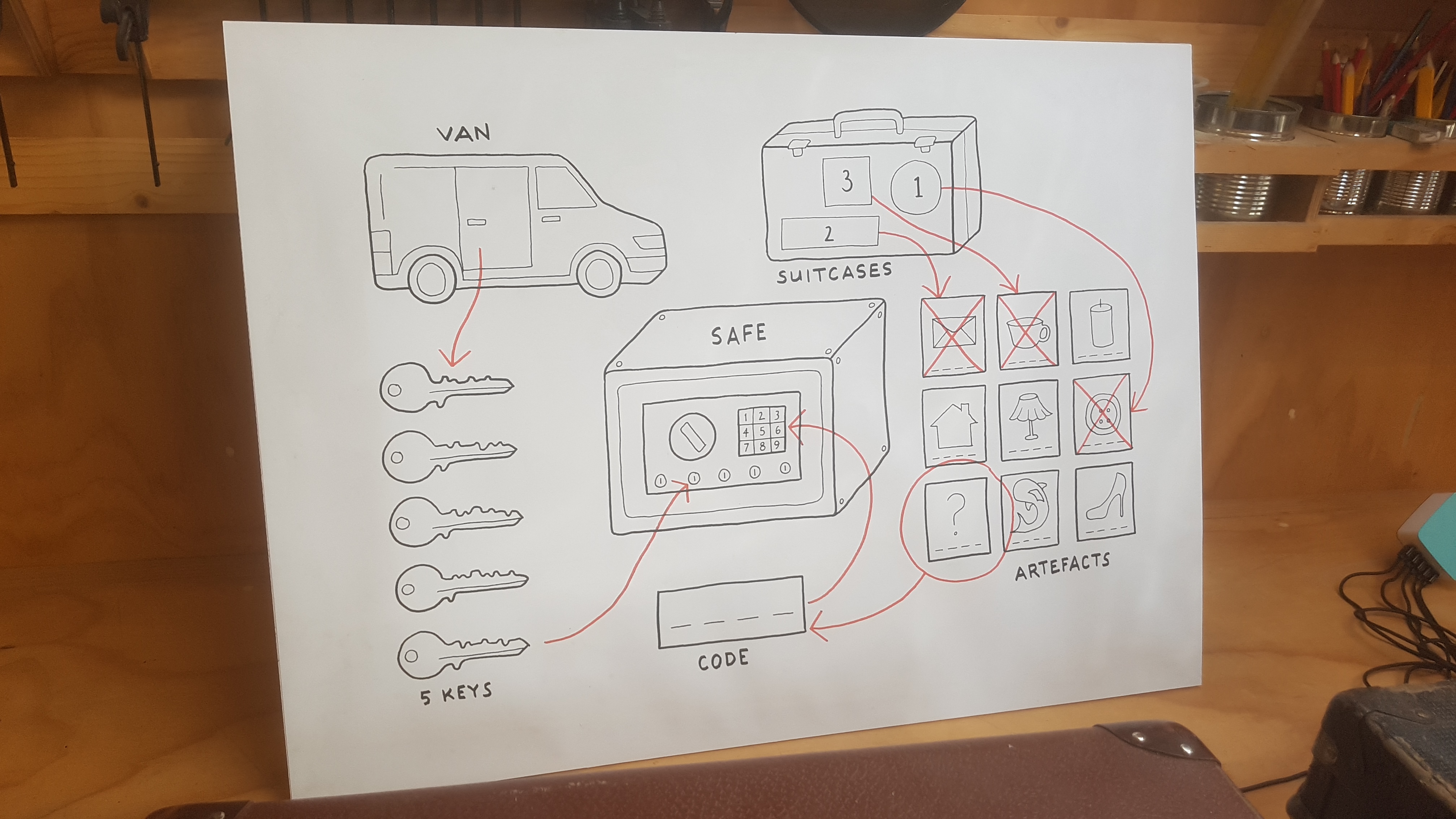
The narrative of the room was essentially that you had to solve puzzles in French so as to find the location of a hidden historic book which had been stolen by a notorious cat burglar. Once you solved the in class suitcase component of the puzzles, you would acquire the code necessary to take out the security camera on the van, retrieve the hidden safe, and find one of the 5 safe keys. The class was broken into 5 groups each with their own suitcase, which once solved gave them access to the van, the idea being that each group would finish at a different time thus preventing crowding and waiting. The early groups could then finish an extra classroom puzzle which would reveal the order in which to put the keys into the safe.
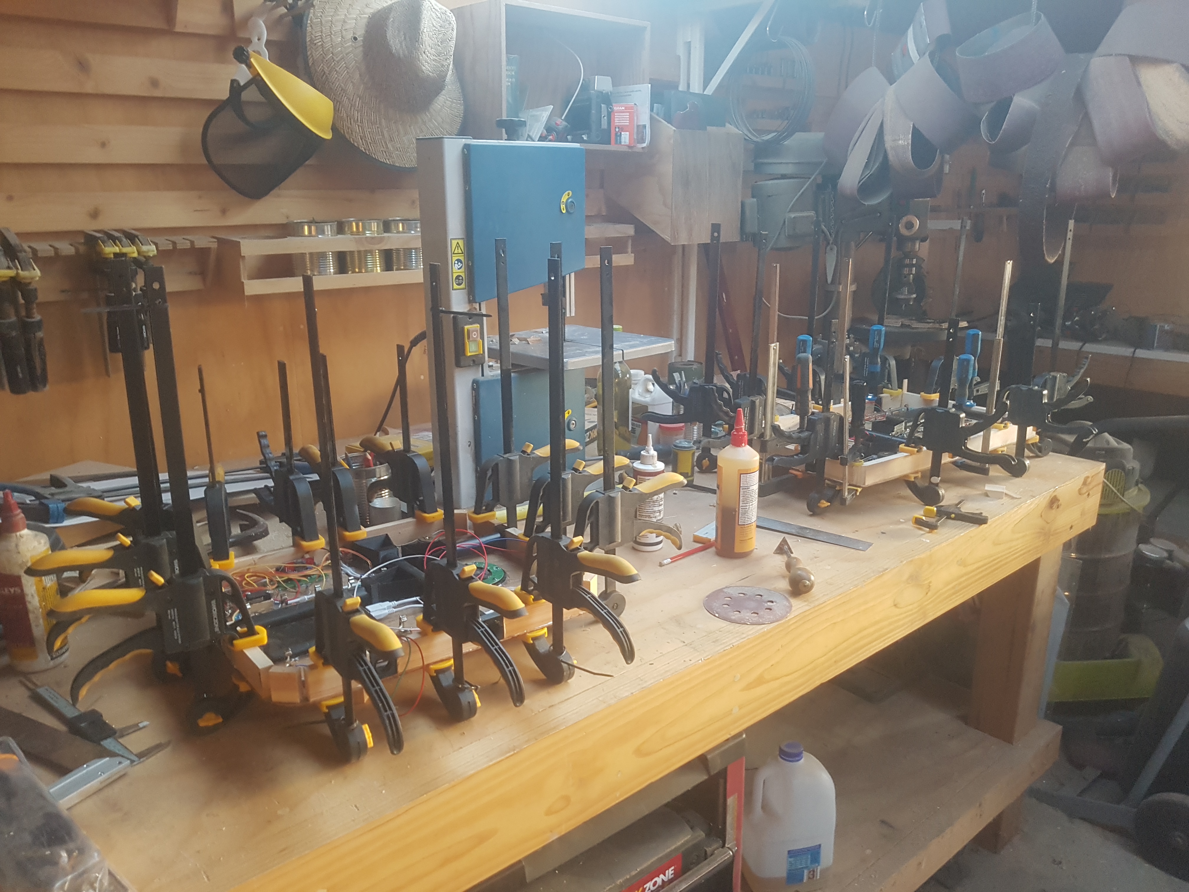
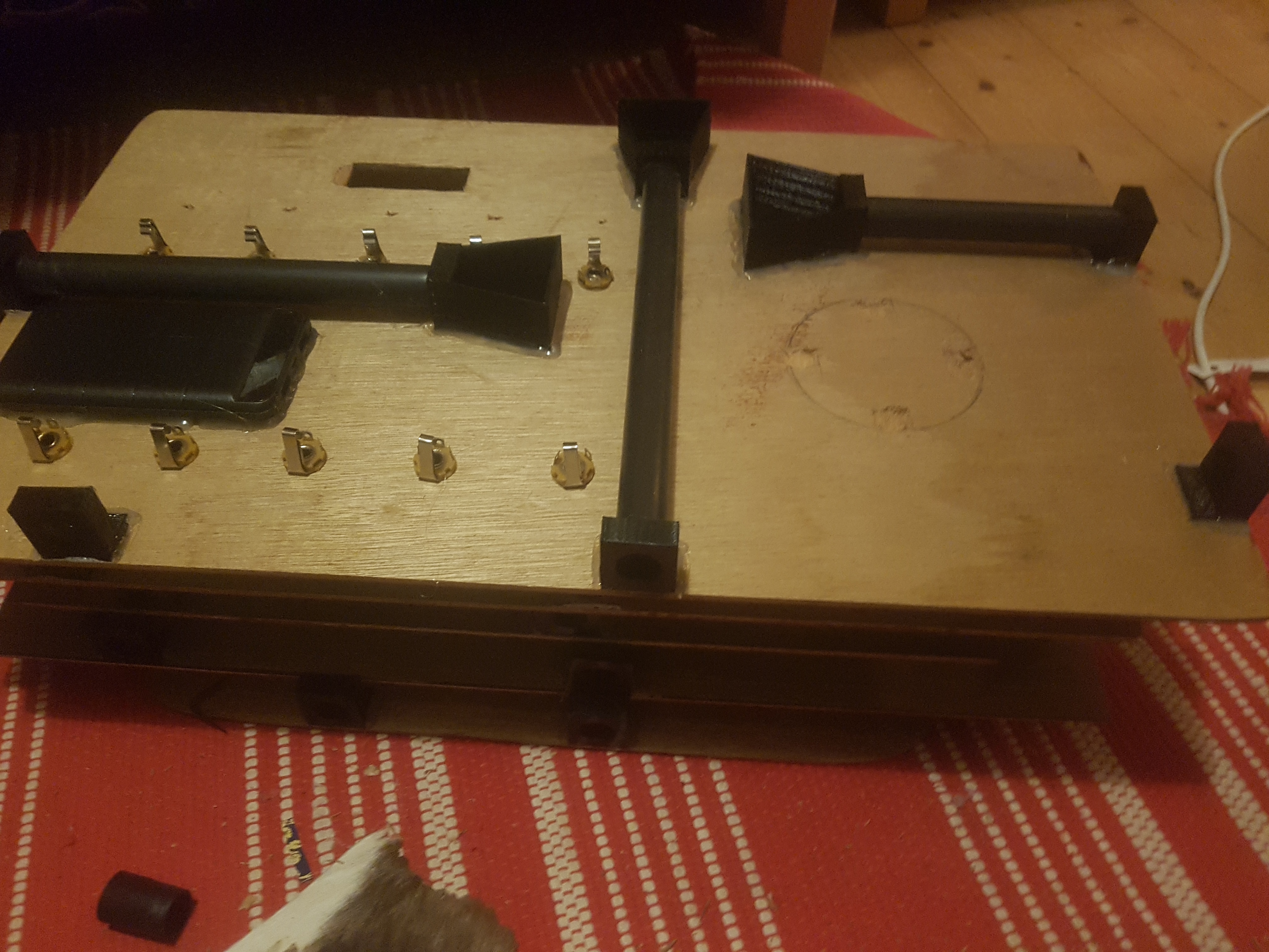
I started out building the suitcase puzzles, which was a little bit of a nightmare as they were all of different sizes, meaning that I had to make each of the plywood insert panels to suit. But with my trusty tape measure, opposable thumbs, and table saw, I managed to cut some nice plywood bases, and support timbers. I glued the support timbers around the edges to not only space the puzzle up giving enough room for the 1/4″ sockets, but also so that there would be something to screw into when mounting them. I think I used enough clamps.
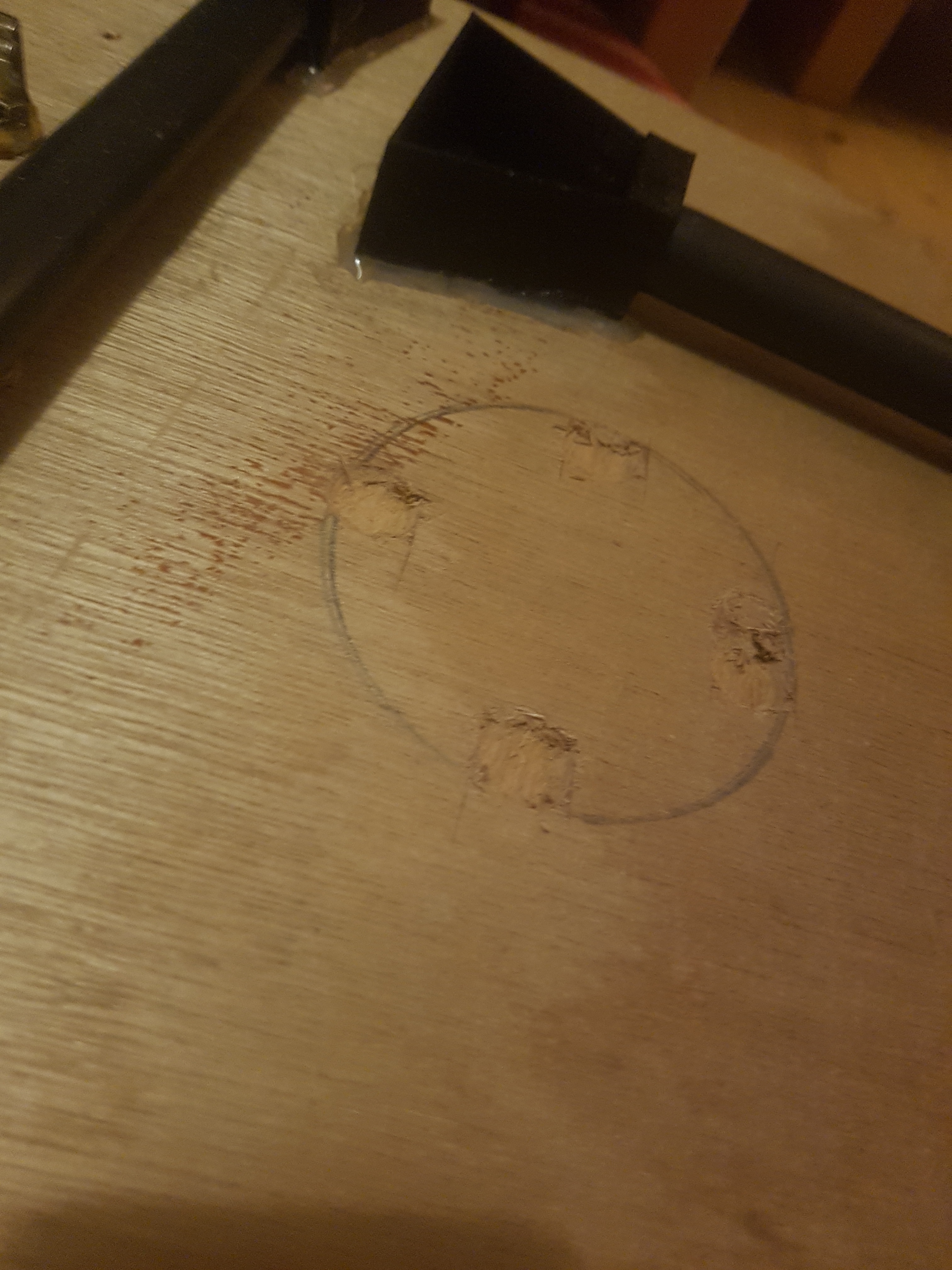
I then carved away four little holes for the neodymium magnets, and then a circle for where the inductive charging pad would fit, all of which would be glued in place. The magnets would snap down the cube puzzle, and also activate the magnetic reed switch inside the cube turning it off when it was sitting in the suitcase… only turning on when picked up.
The inspection camera puzzle pipes and 3D printed chambers were also glued on, and the 1/4″ sockets fitted… as you can see, I’m just using a common, off the shelf USB power bank to power this with.
The next part was mounting the screen, arduino, MP3 playback module, speaker, switches, magnets, inductive charger, magnetic charging port, and the power switch.
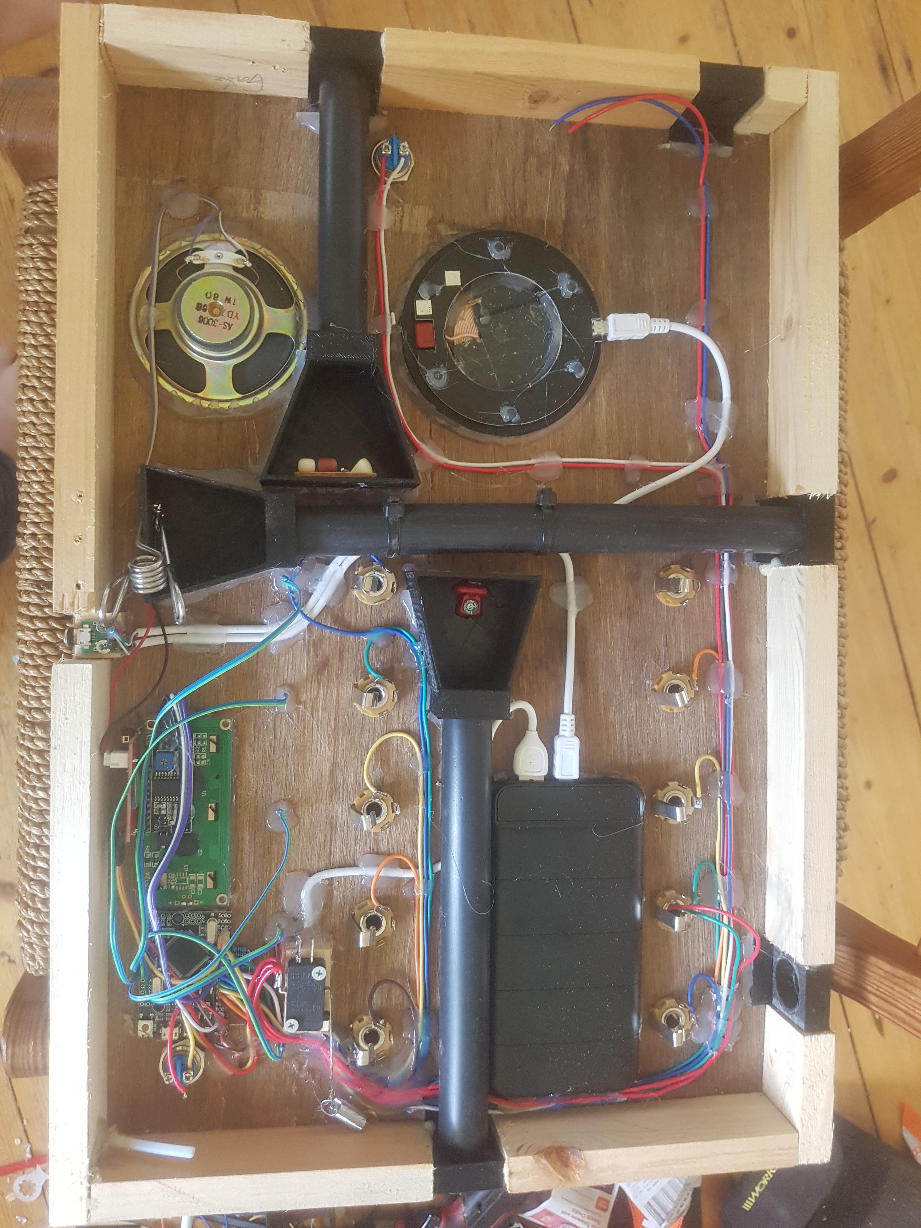
The inductive charger and power bank both get powered when the suitcase is connected to its magnetic charging cable, this way both the suitcase and the cube get charged at the same time… a little spring on the switch prevents it from being broken should someone pull the string too hard, and give a much greater string pull to turn it on with.
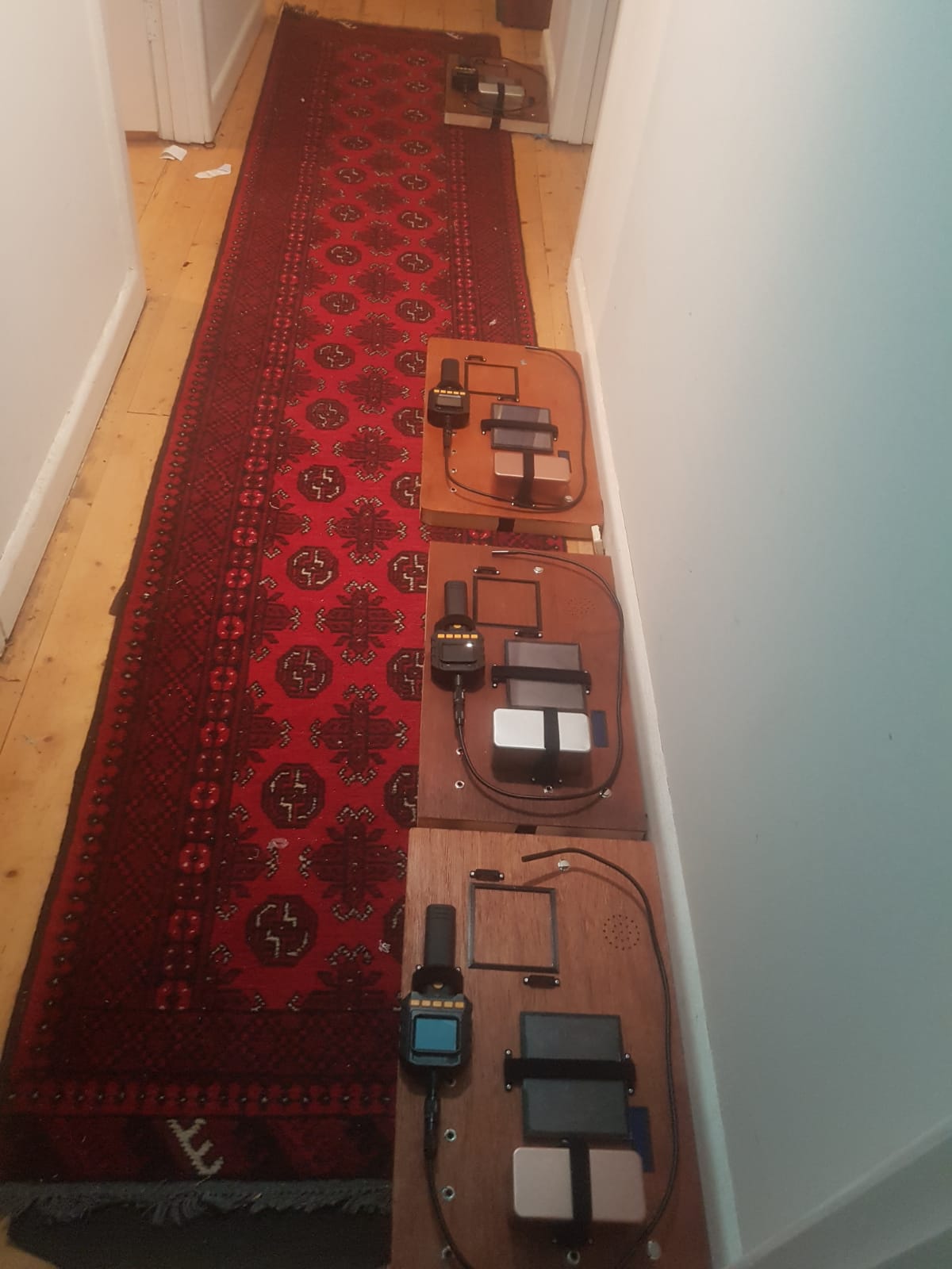
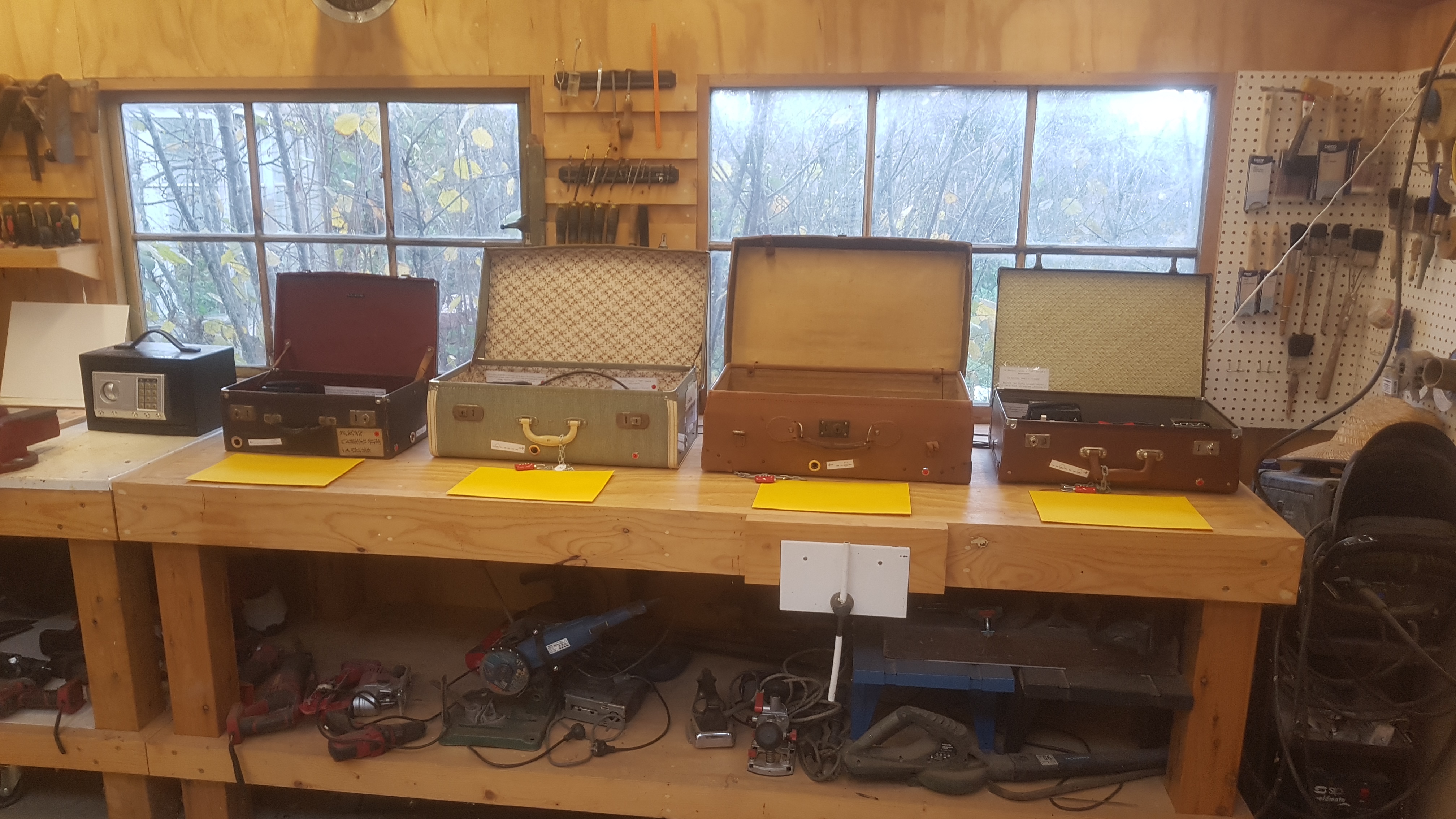
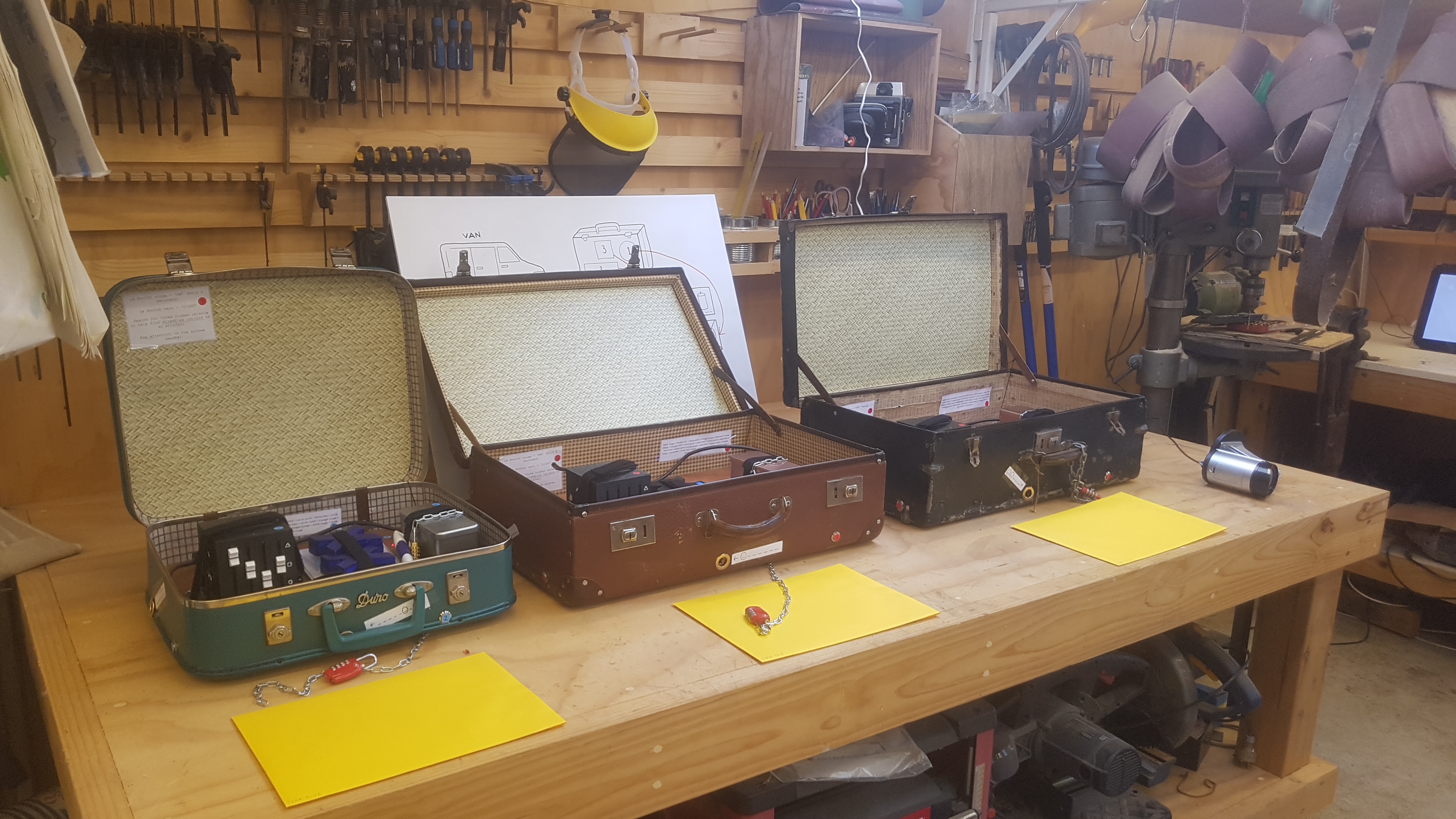
They slowly started to populate my corridor, little 3D printed brackets held all of the puzzle components to the board using double sided velcro straps, a little surround was glued on to align the cube with the magnets and inductive charger.
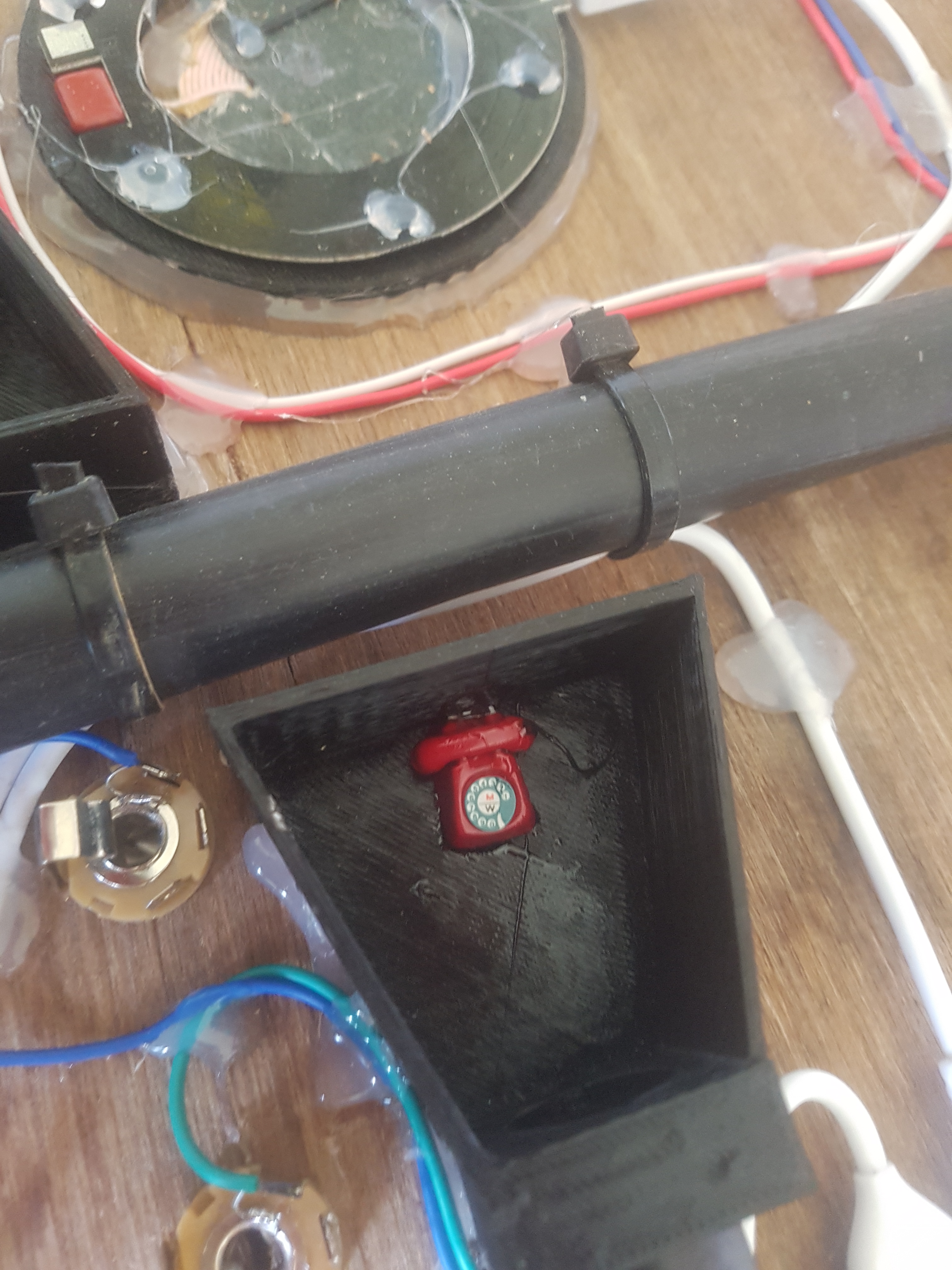
The little inspection camera puzzle figurines were carefully glued in place so that they were easy to view, and then closed up.
Once the bases were fitted into the suitcases it was just a matter of putting some nice brass eyelets over the inspection camera puzzle holes, and fitting the two external audio switches…
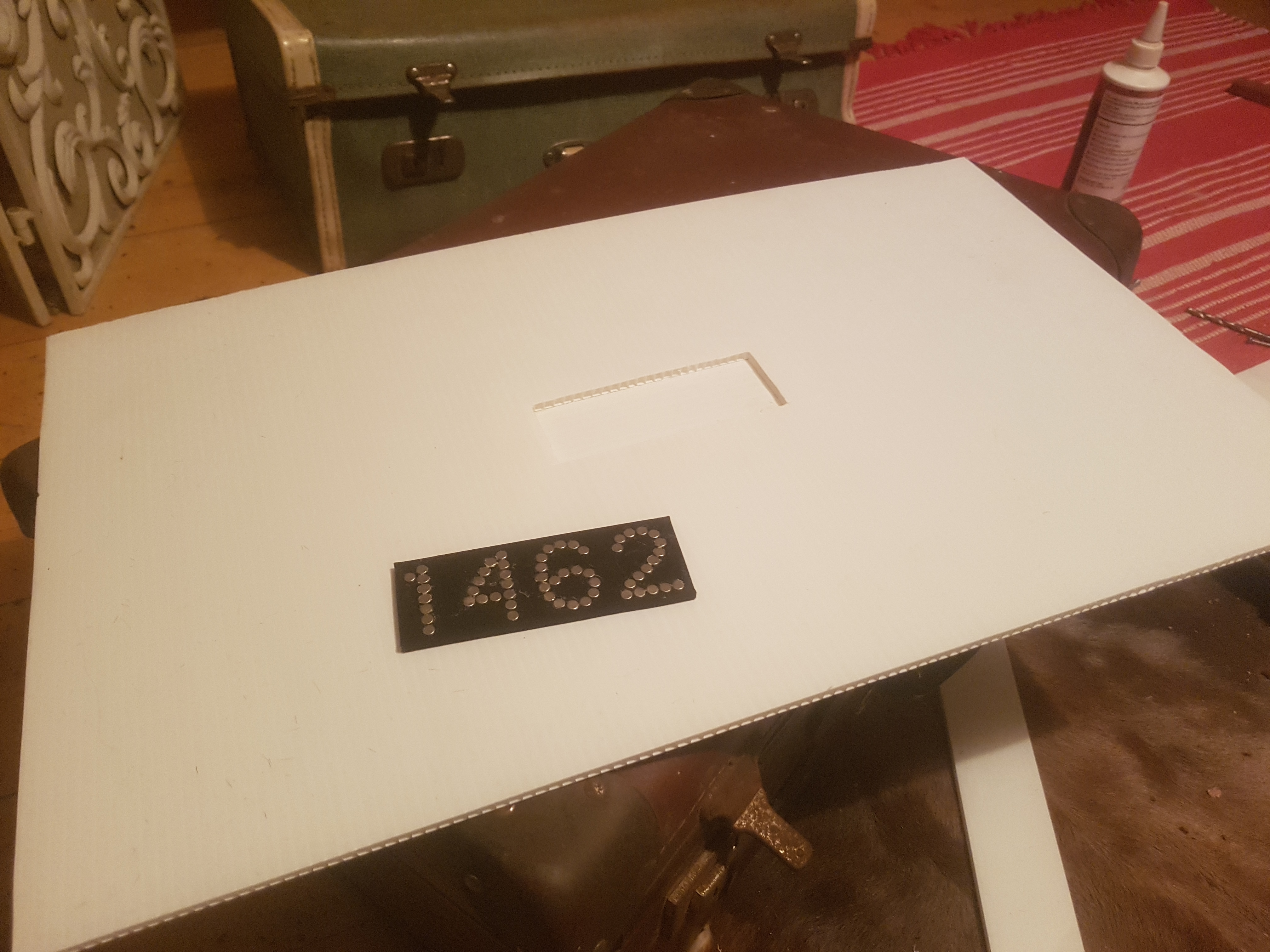
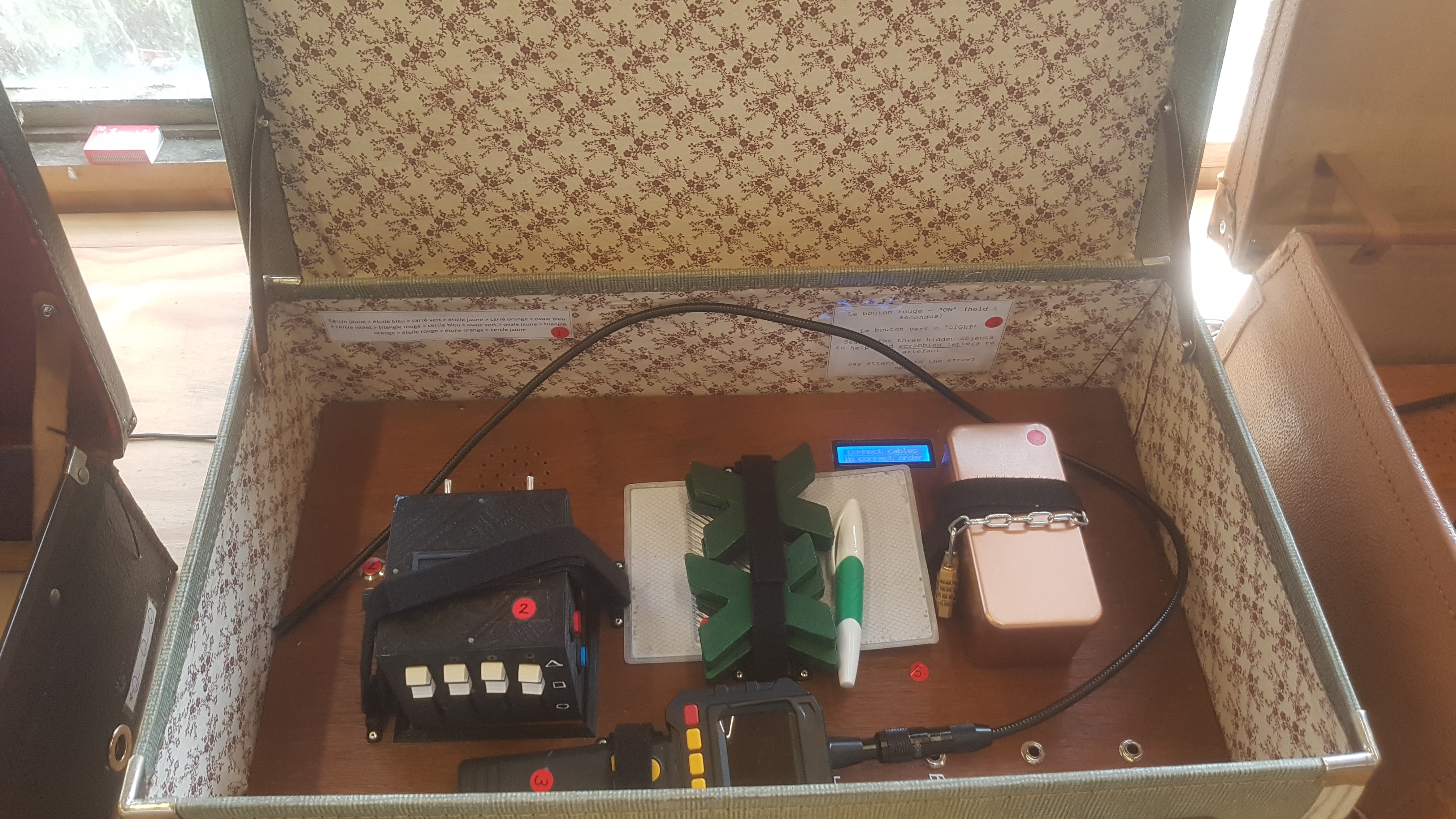
I almost forgot the magnetic number puzzle lid, which was a heap of small neodymium magnets pressed then glued into a 3D printed holder, and hidden behind a layer of cardboard in the lid, some were fabric covered, others vinyl covered . The point to point switchboard puzzle and LCD screen are very similar to one of my previous switchboard puzzles with the exception in this case that the arduino would also monitor 4 buttons for the audio puzzle, and then communicate those button presses to an MP3 module using serial, which is super simple to do.
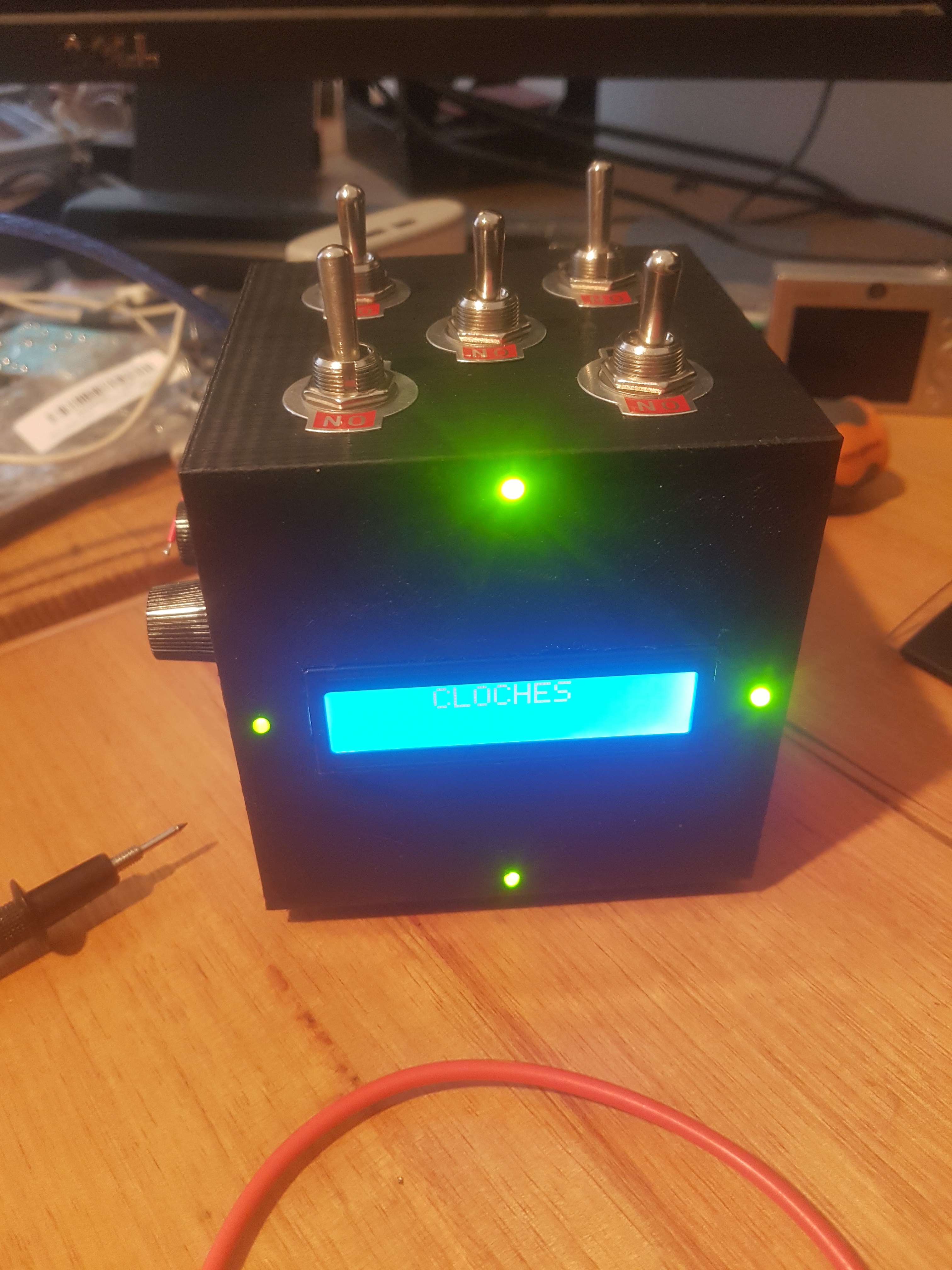
The cube was a whole new degree of fuckery, it was entirely 3D printed at 100% infill for maximum strength, and had 4 bi-colour LED’s on the front on each edge surrounding an LCD display.
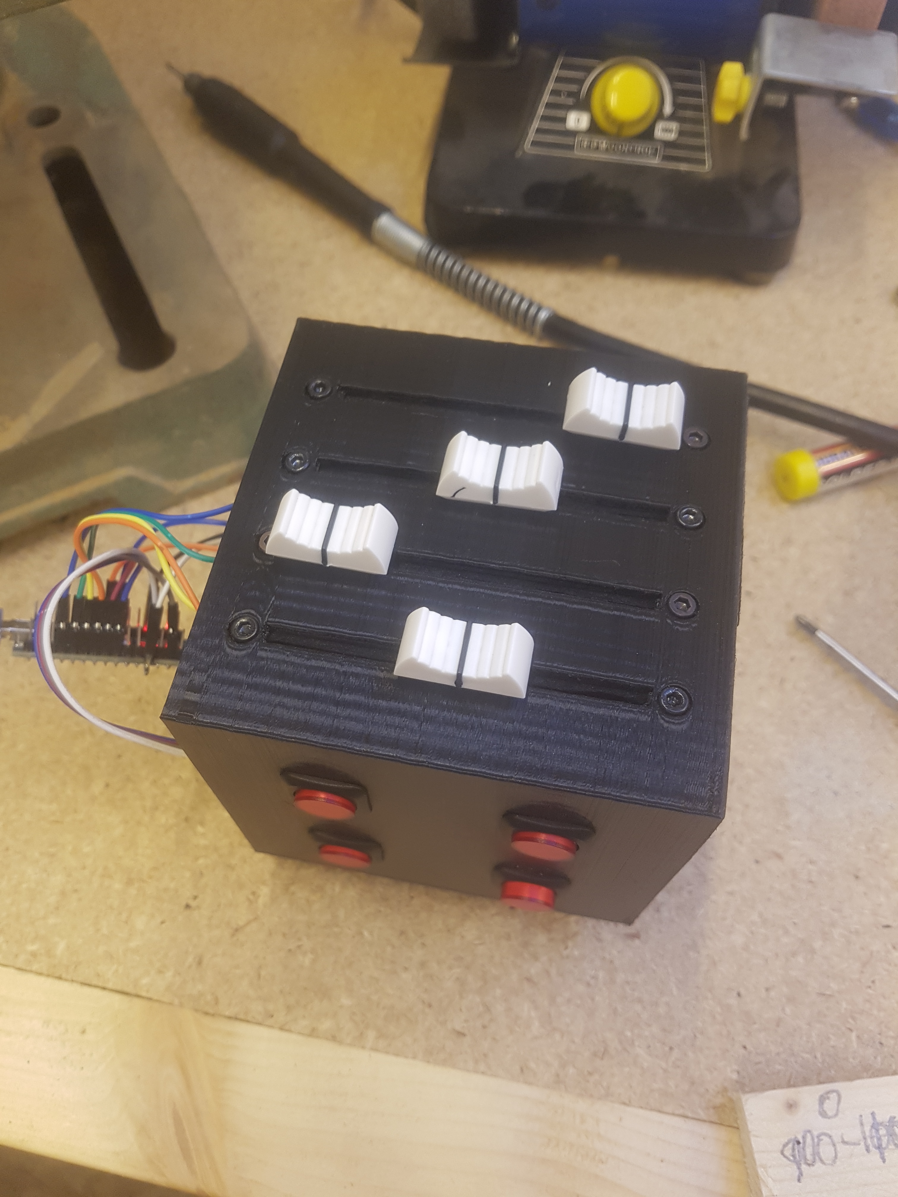
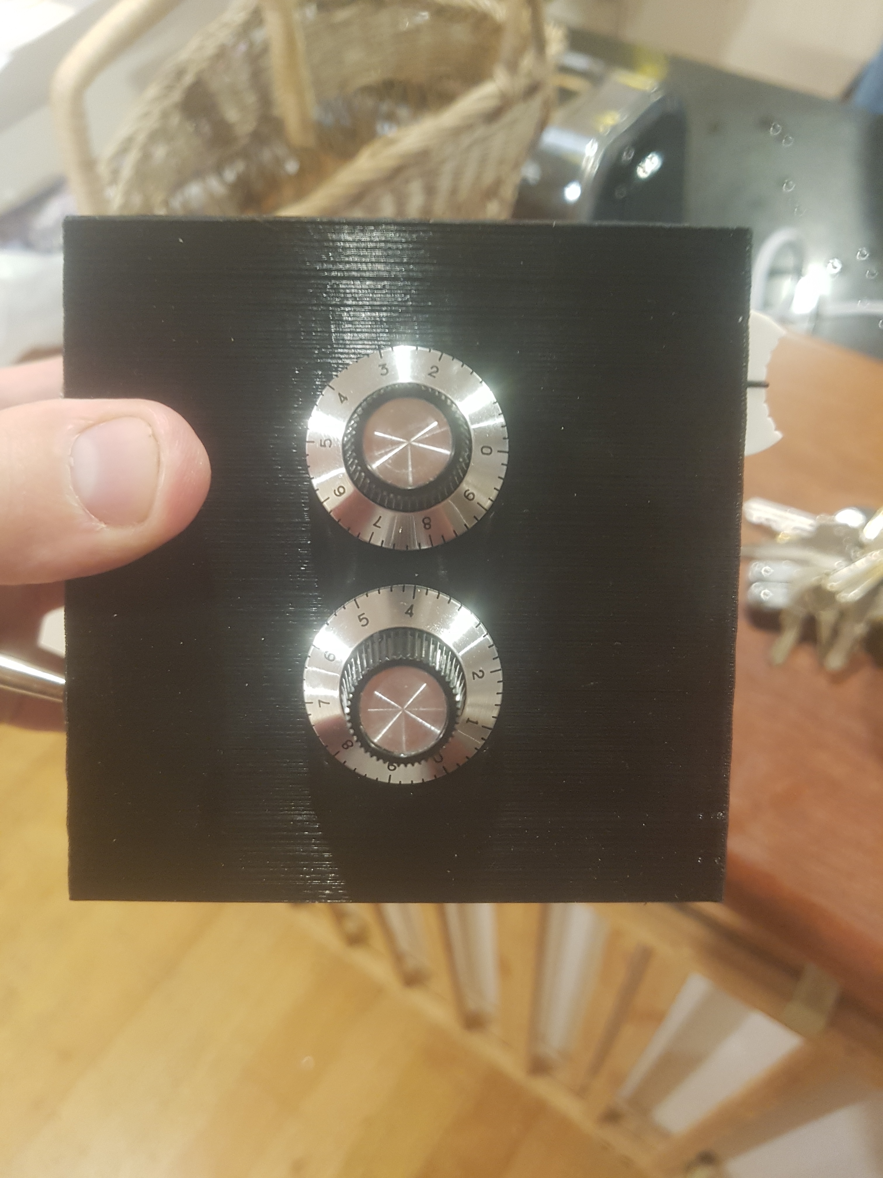
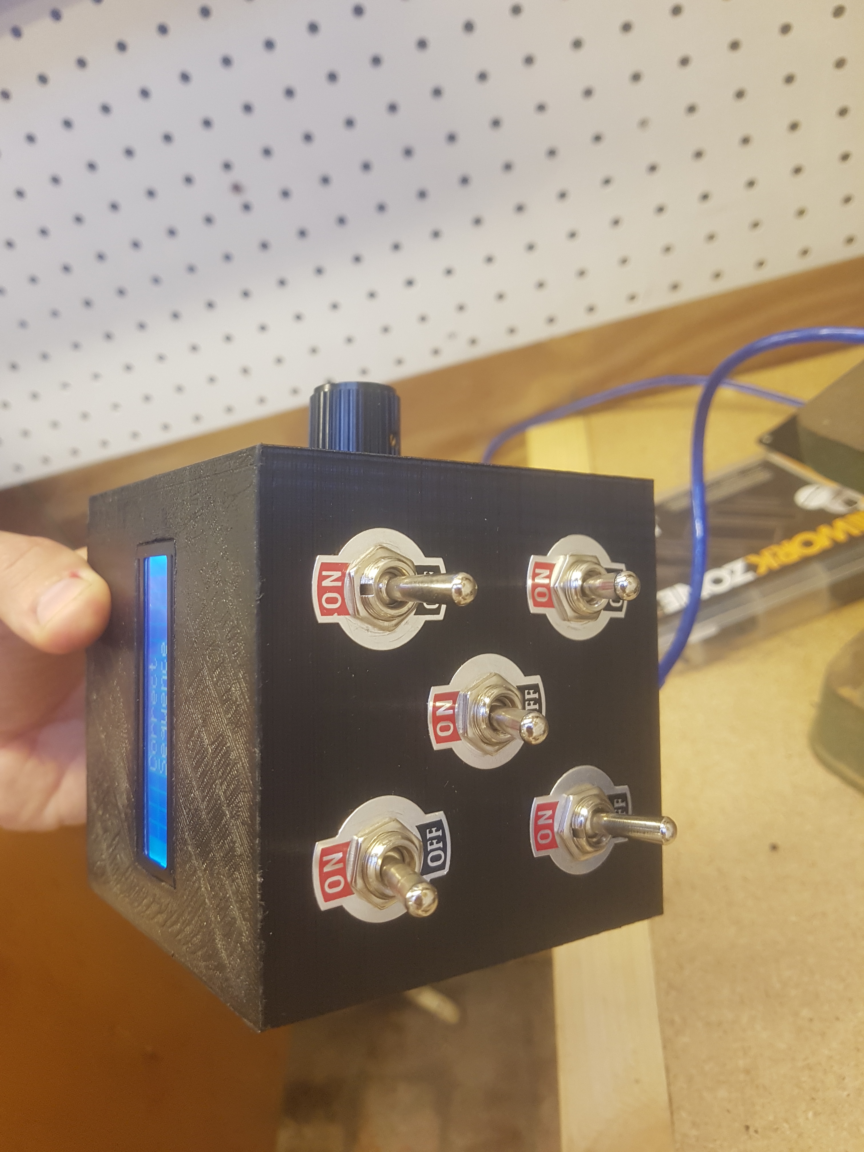
Each of the four sides had either 5 toggle switches, 4 illuminated push buttons, 4 sliders, or two rotary switches.
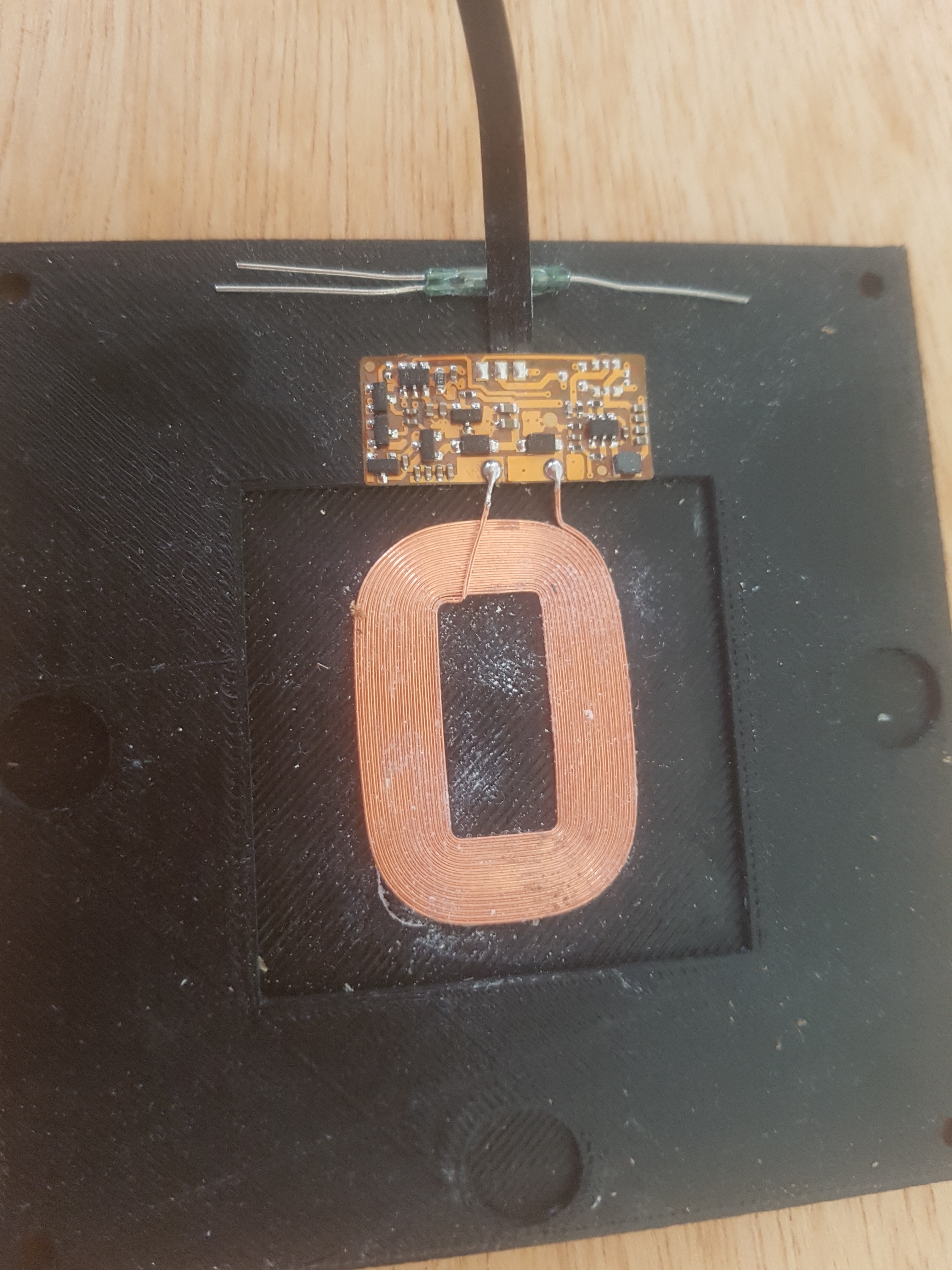
While the bottom housed the inductive charging pad, magnets, and magnetic reed switch to activate the cube when it was lifted from the suitcase base.
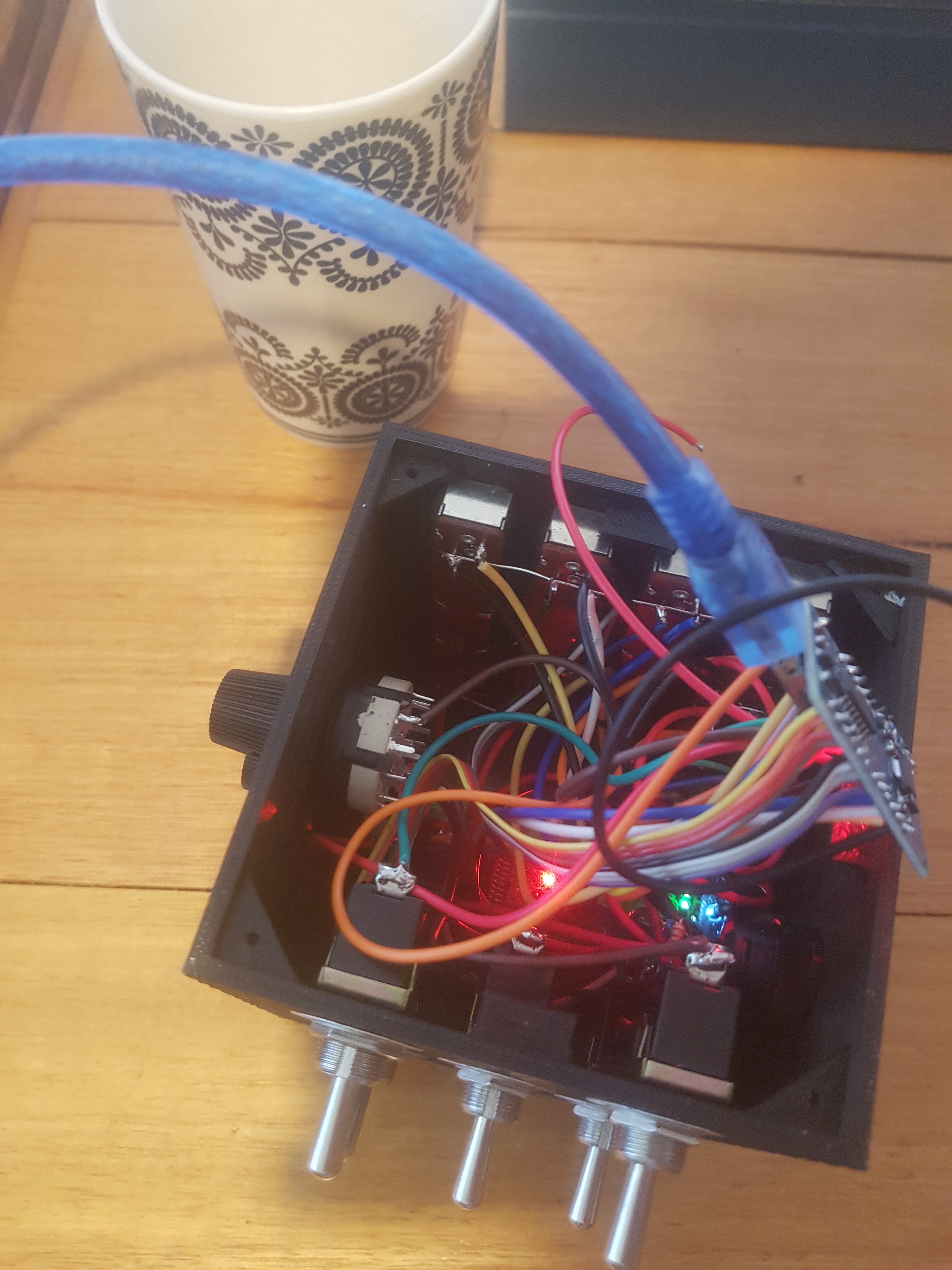
I was determined to use an arduino nano without any extra complications, so managed to get all of the inputs and outputs down to 13 pins. The programming was as simple as you would expect, using analog inputs for the sliders, and giving them very generous limits. A little lithium mobile phone battery battery powered the whole thing using a little charging board… I’ll find a picture of it one day.
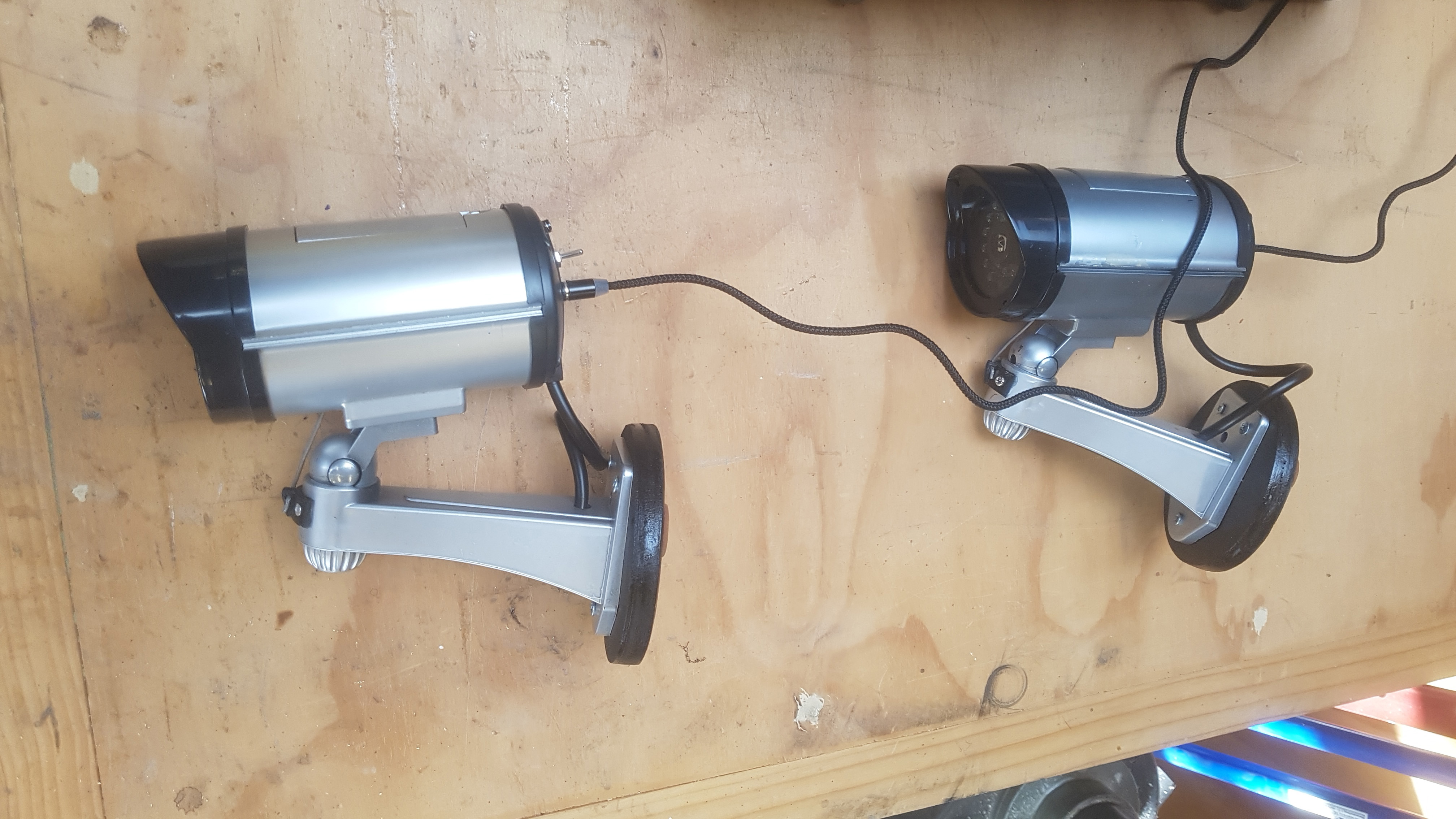
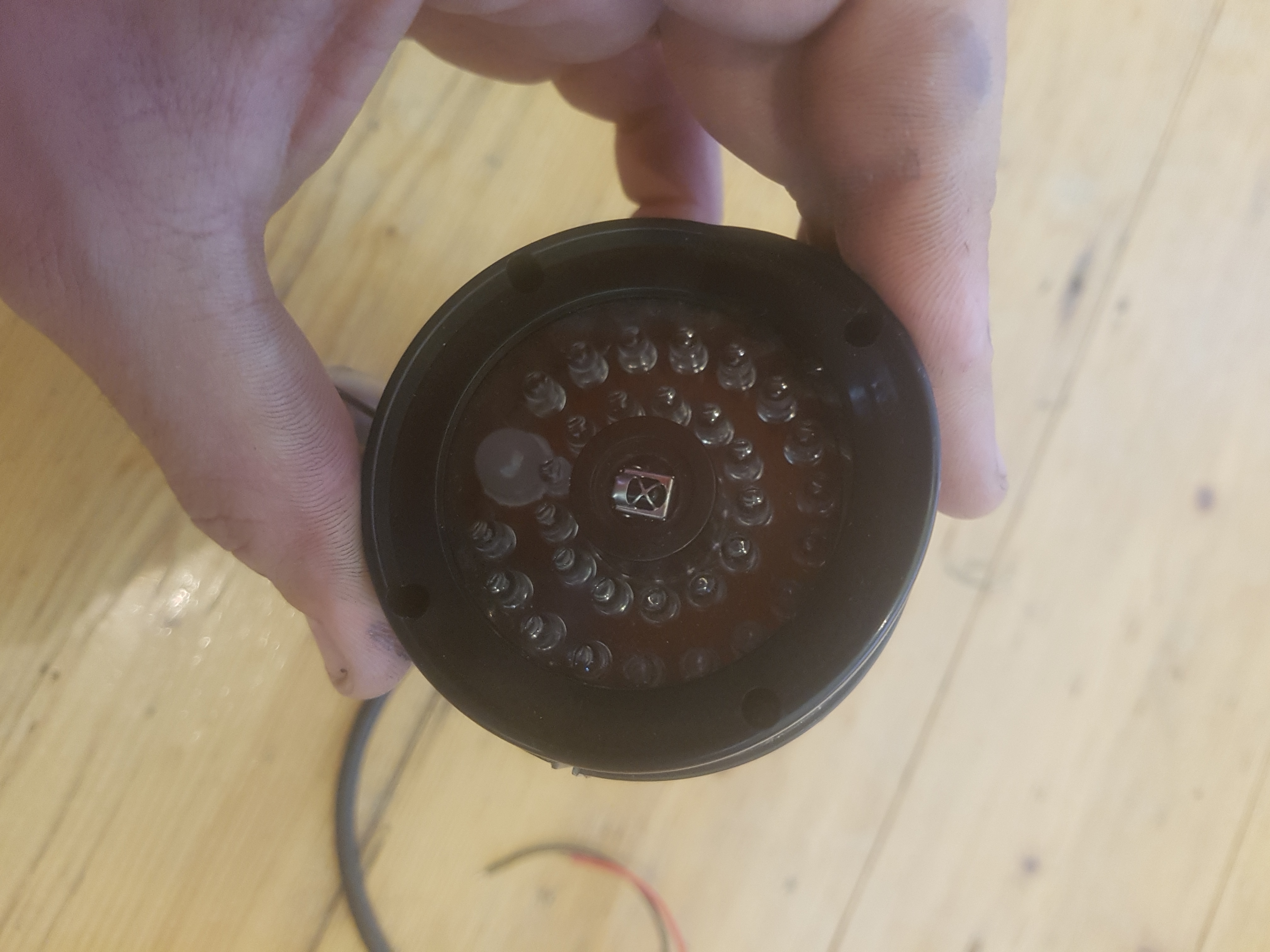
The cameras were a bit of fun, inspired by Metal Gear Solid, a green light on them would turn red and they would sag down when shot with an infrared gun. This was achieved with an infrared receiver, an arduino, and a servo.
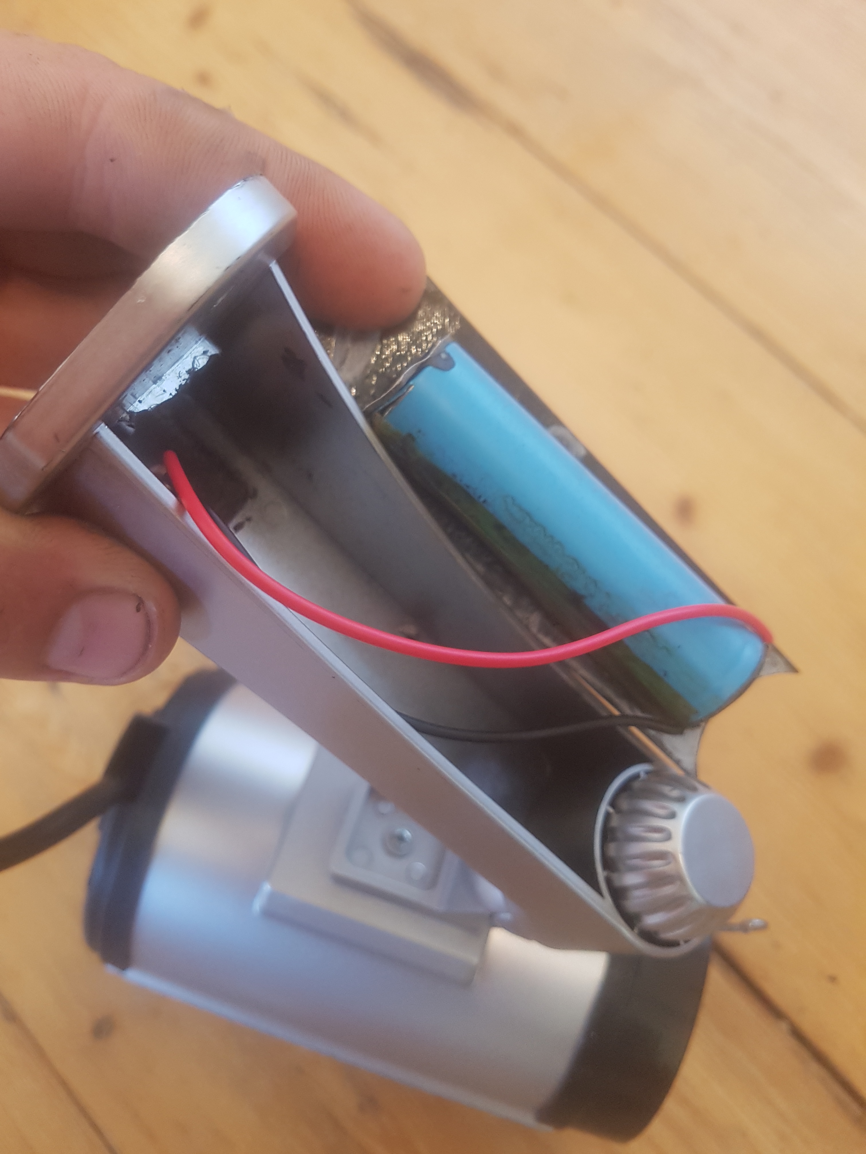
A lithium battery and charging circuit from a power bank was used to power the circuit, and it, just like the suitcases had a magnetic charging port on its back.
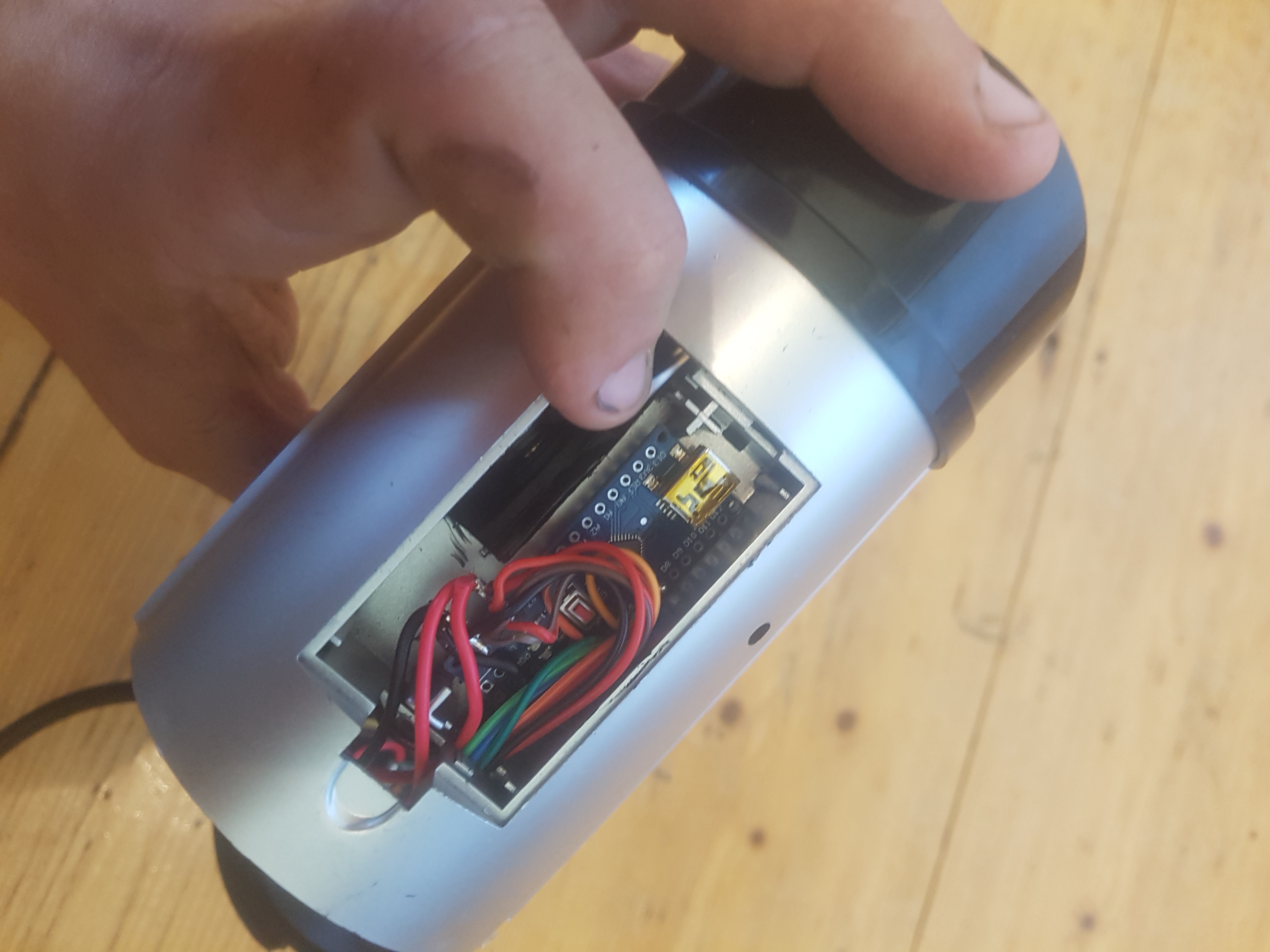
An arduino was housed up in the old battery compartment for easy access when debugging.
A giant neodymium magnet glued into a plywood base with rubber non skid pads secured the camera to the side of the van.
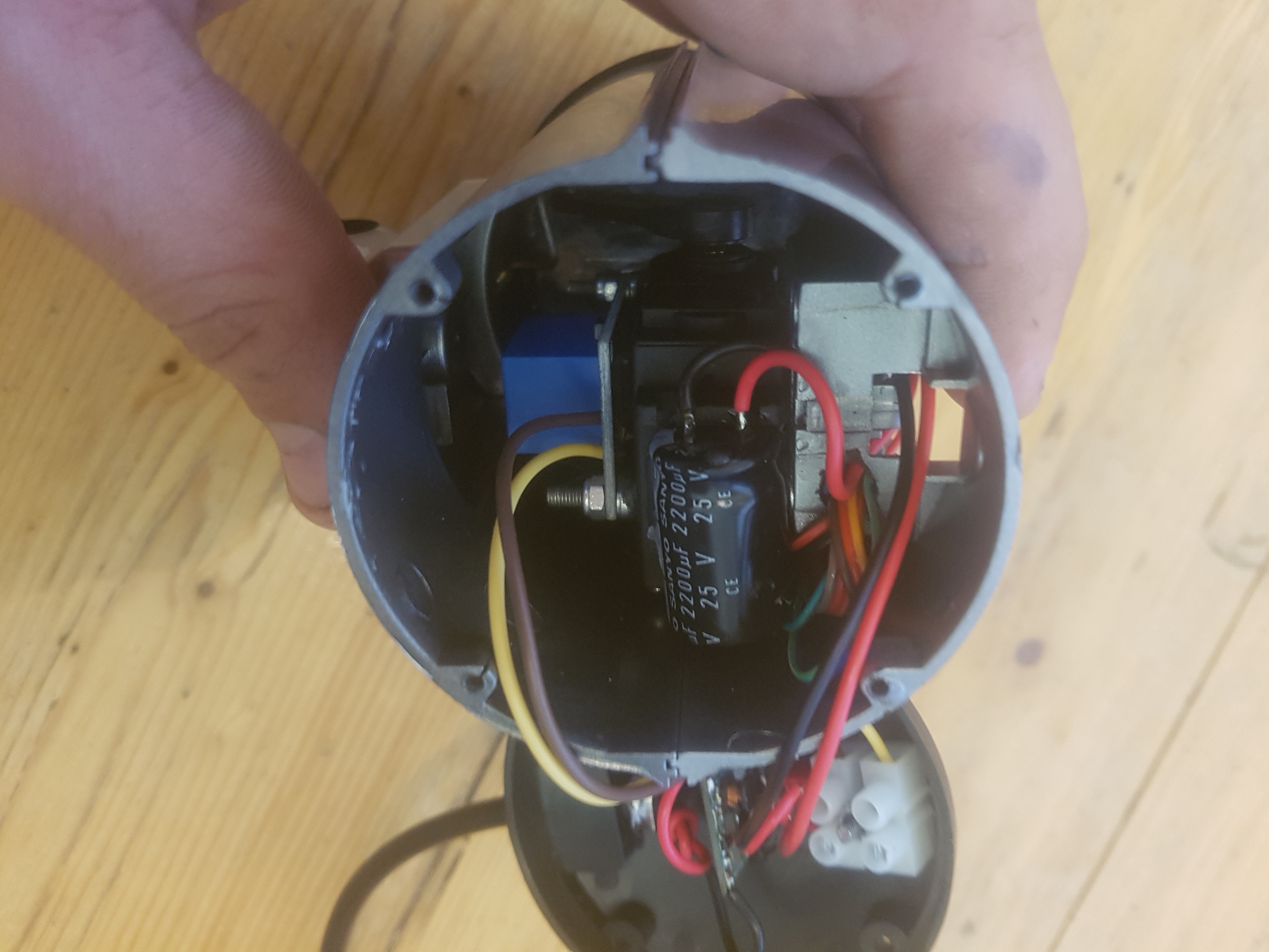
A smoothing capacitor prevented any noise from the servo getting to the power rails which drove me nuts trying to debug.
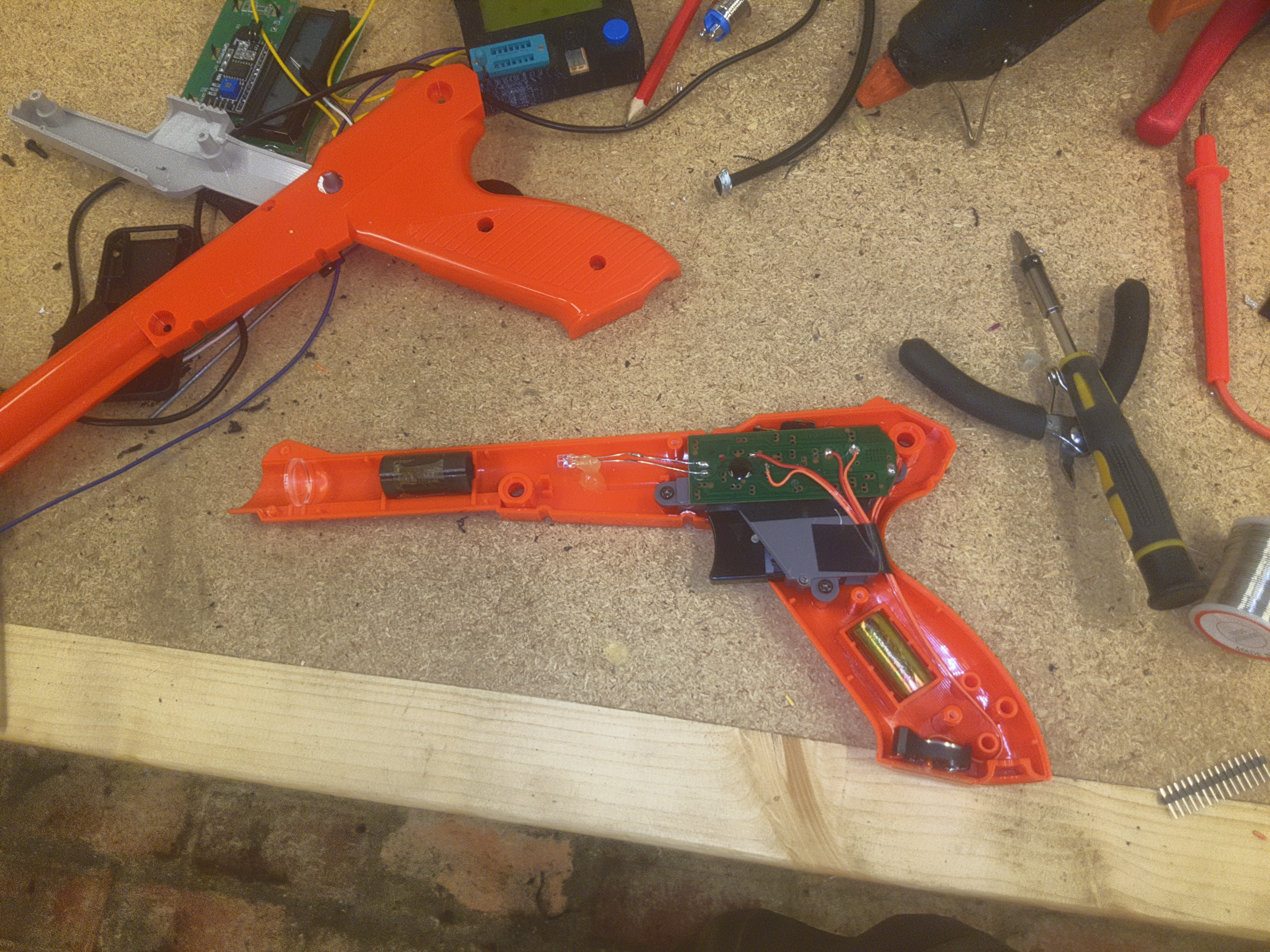
The infrared gun was built on the iconic Nintendo Zapper, because anything else would have been a crime against humanity.
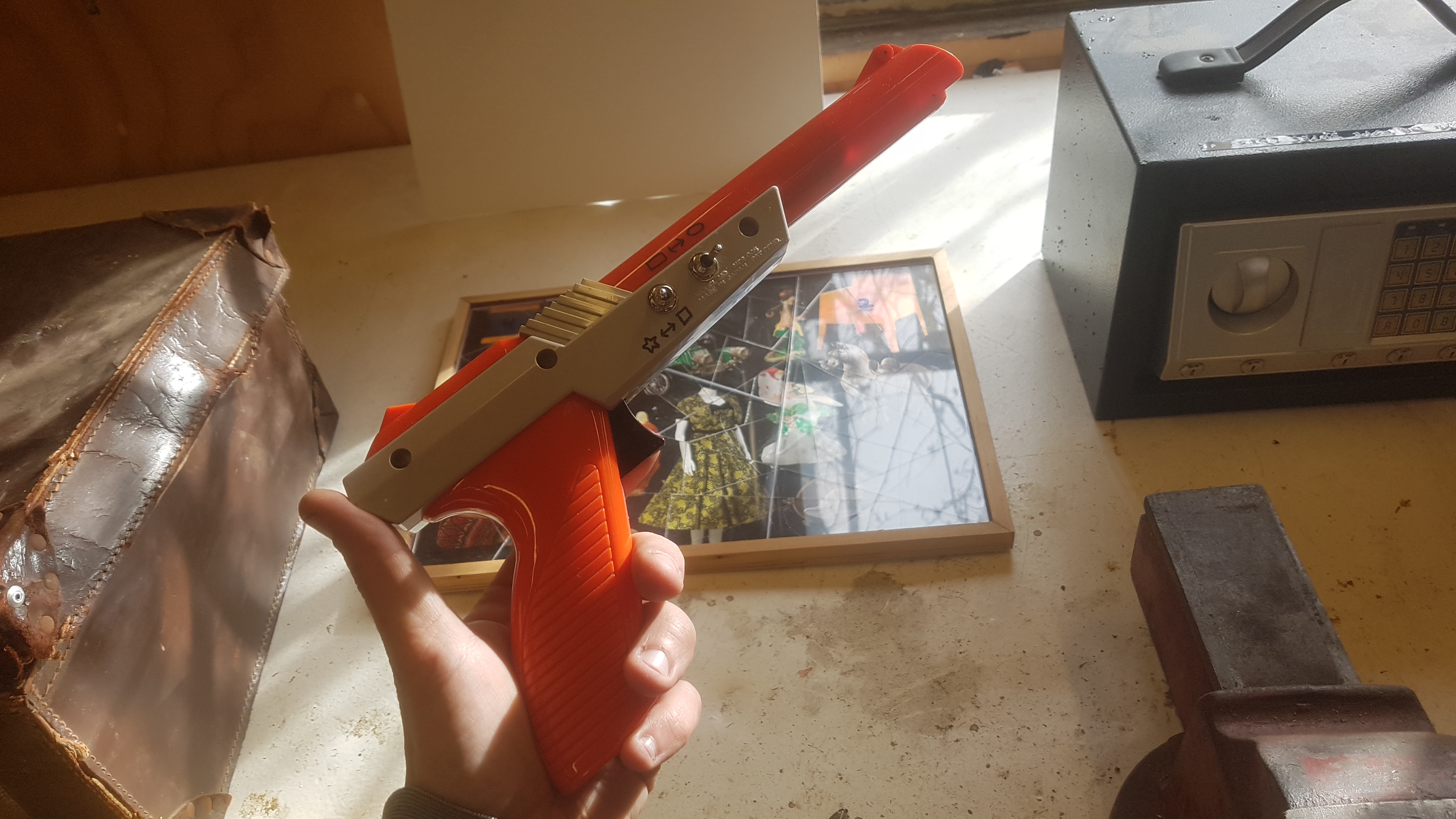
I simply mounted a generic remote control board inside, wired it up to the trigger, and then wired the battery up to the puzzle switches on the side. To get a more focused beam from the IR diode, I ground the tip of the diode flat, then polished it.
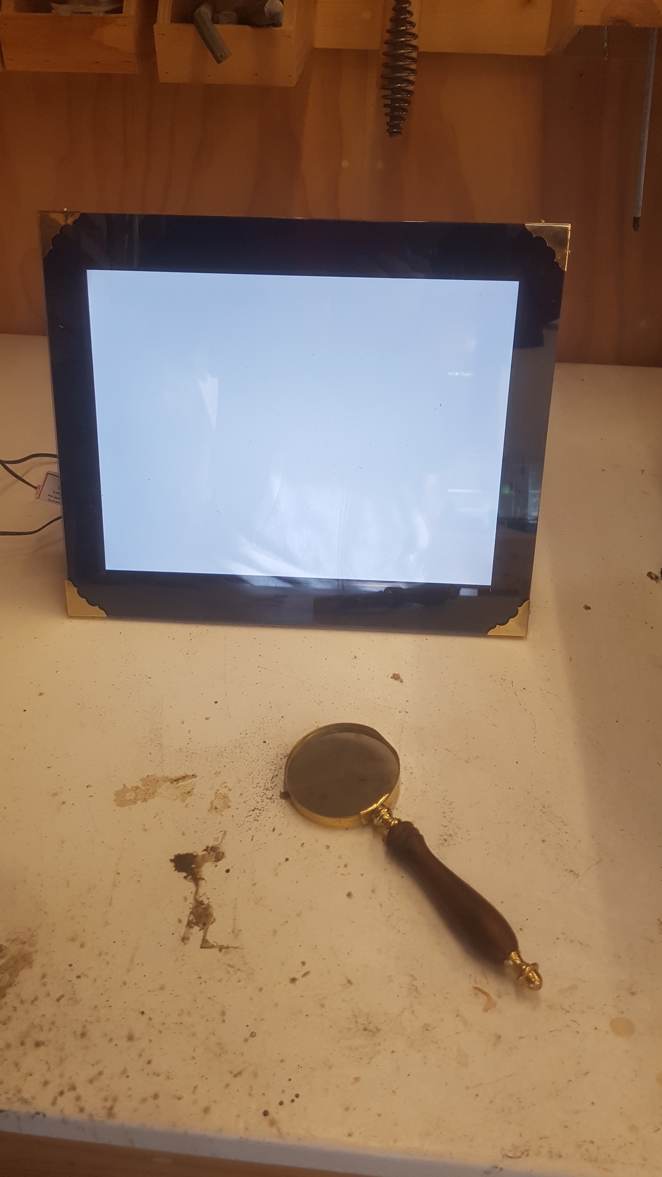
The screen puzzle was a nice fun one, when you remove the polarizer from the front of an LCD screen you end up with just a block of white light with no distinguishable image… which makes it perfect for secret letter puzzles.
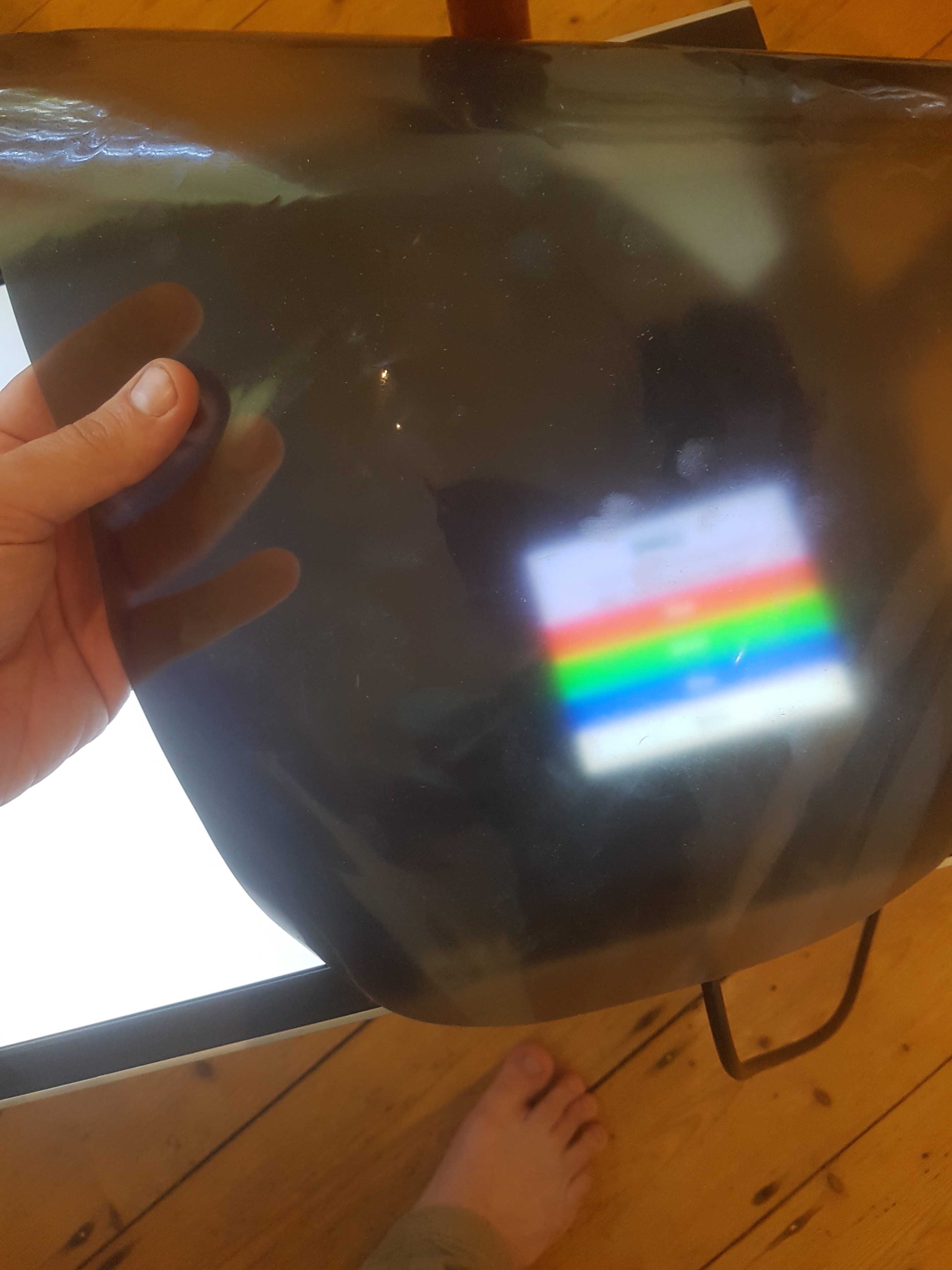
But the orientation of the polarizer also changes the colours of the image being displayed… so it allows you do add a rotational variable into the puzzle. In this case you would be shown the orientation of the magnifying glass, and given the colour, you would then have to search for a number of that colour while holding the magnifying glass in that orientation.

A portable LCD photo frame made the puzzle super simple to set up, despite the process of removing the polarizer being a nerve-wracking one… isopropyl alcohol behind the film actually makes this pretty easy.
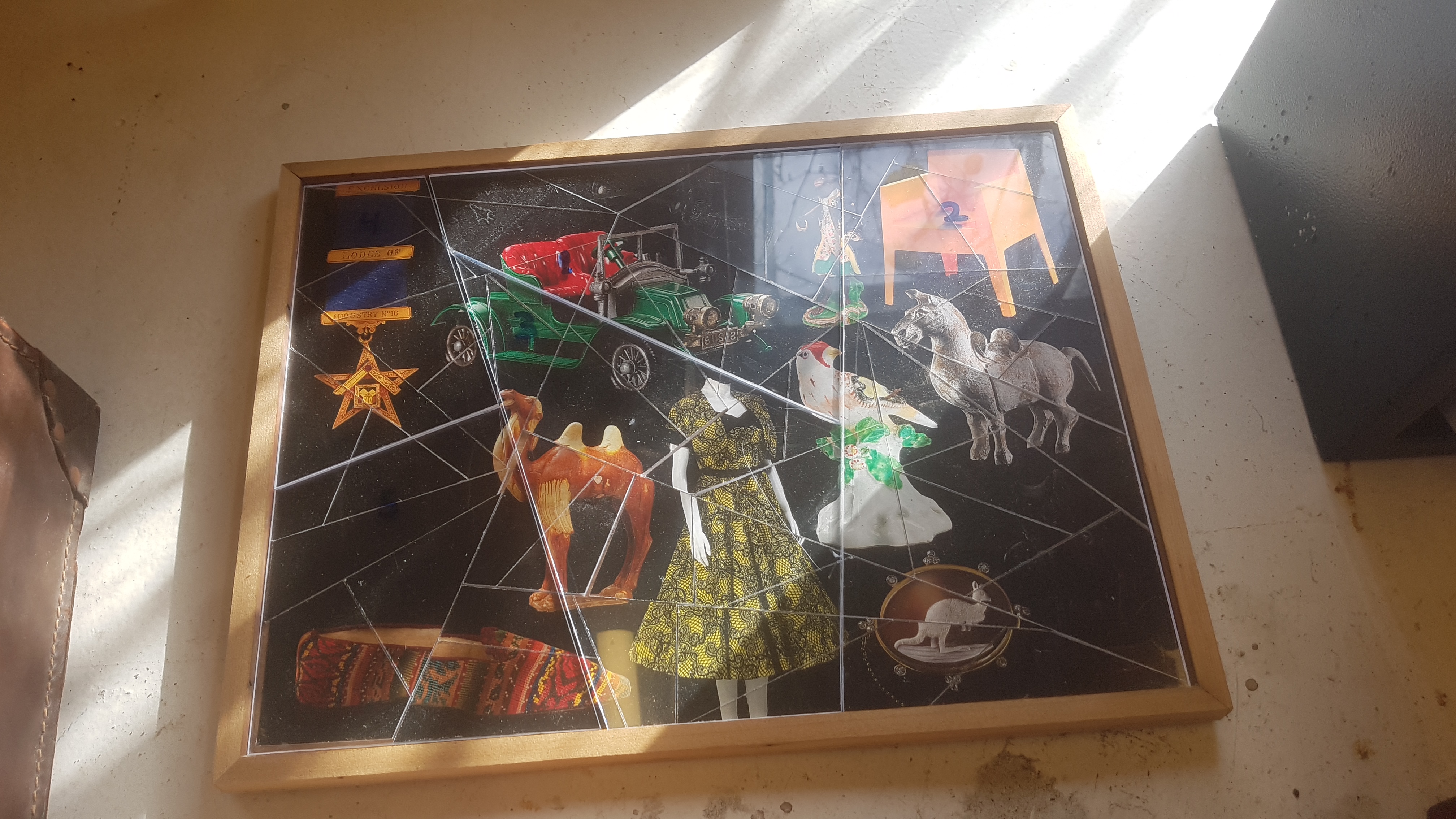
There was a dual layer jigsaw puzzle that was used as a puzzle for the faster groups to work out the key order for the safe, it was just a dye-sub print laminated onto plywood for the first layer.
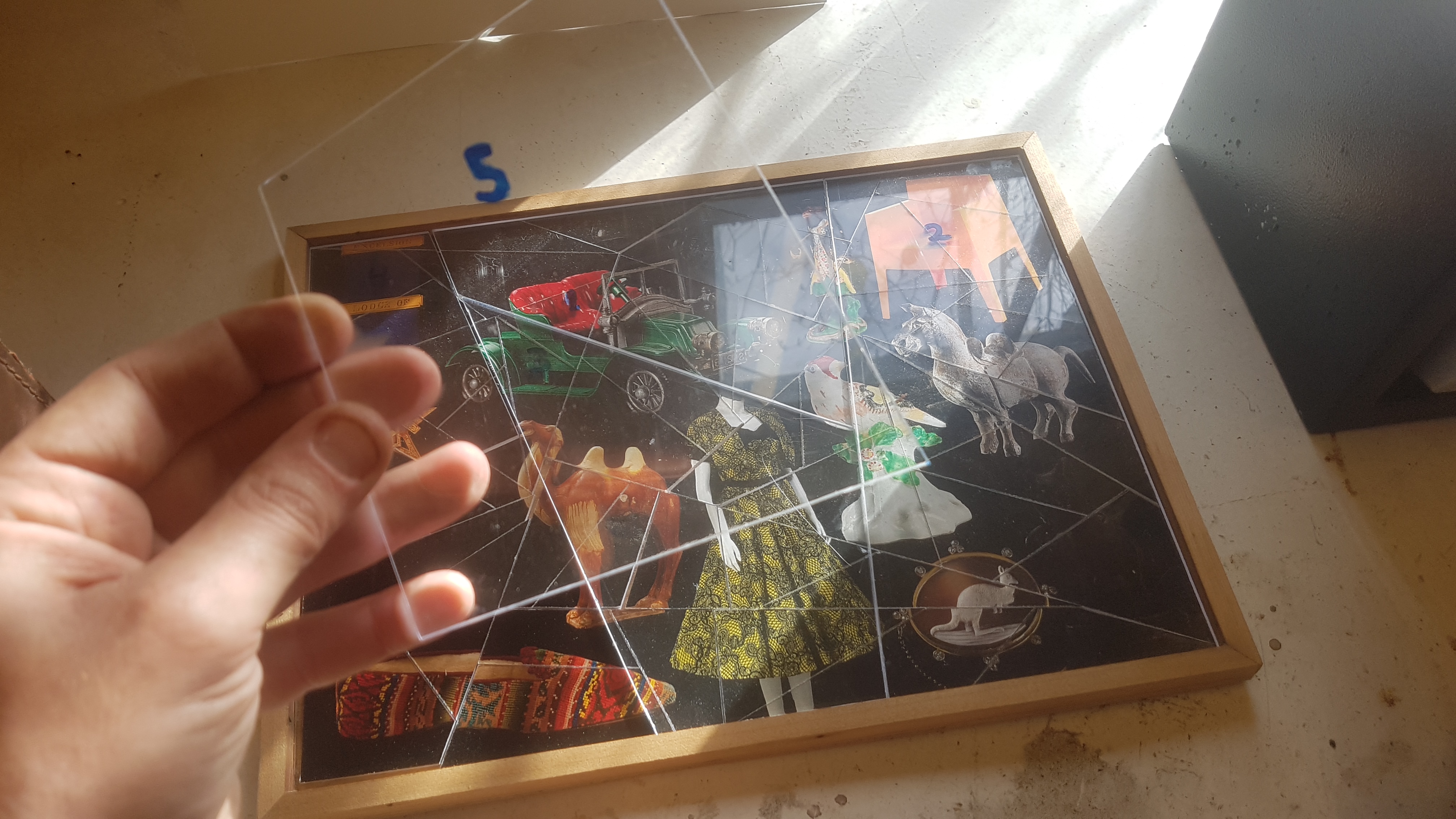
While the second layer was a clear polycarbonate overlay with the sequence number written on it, the colour behind the number would determine which colour key was to be used, it’s far from high tech, but it worked really well and seems to have been indestructible.
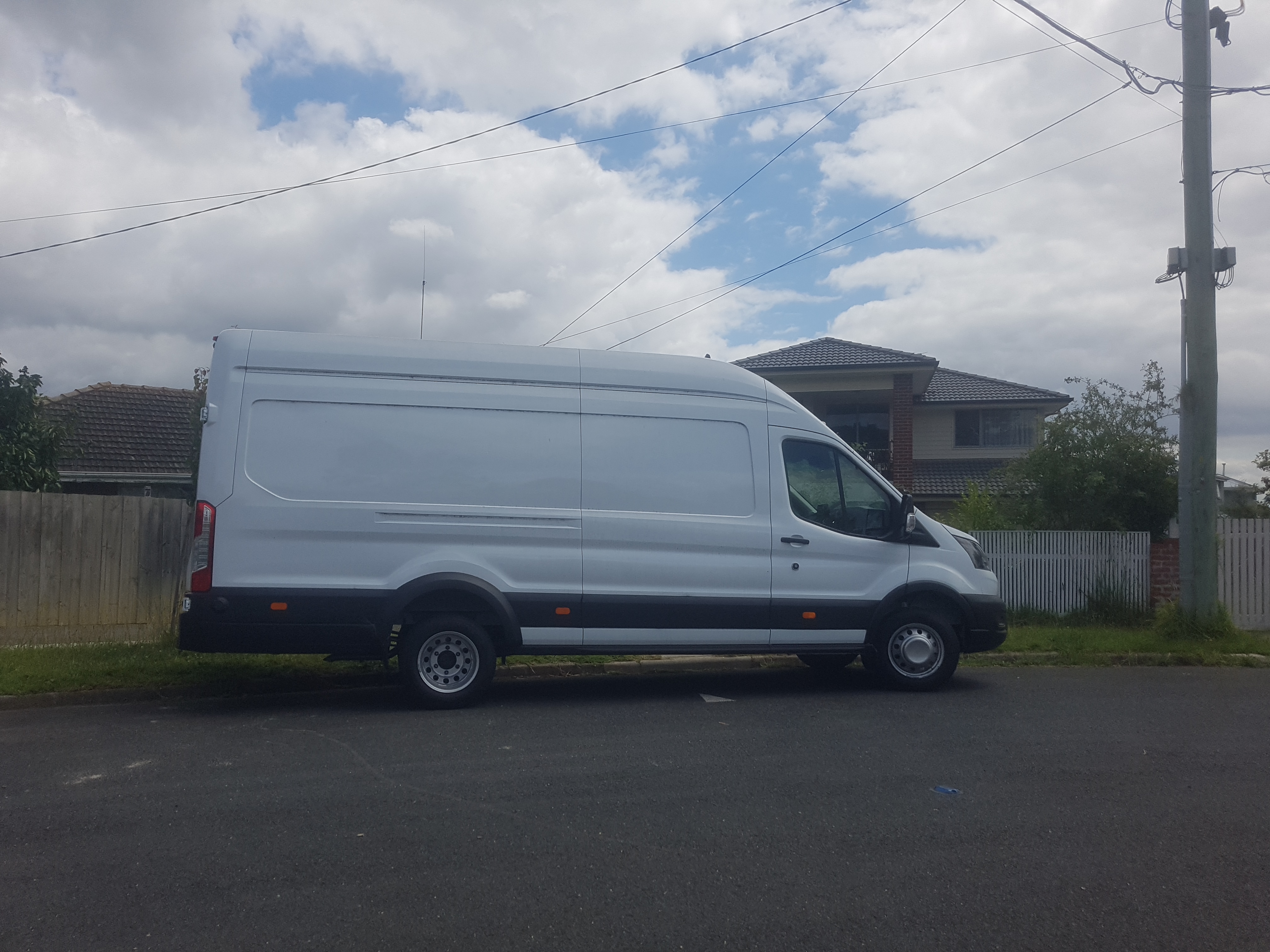
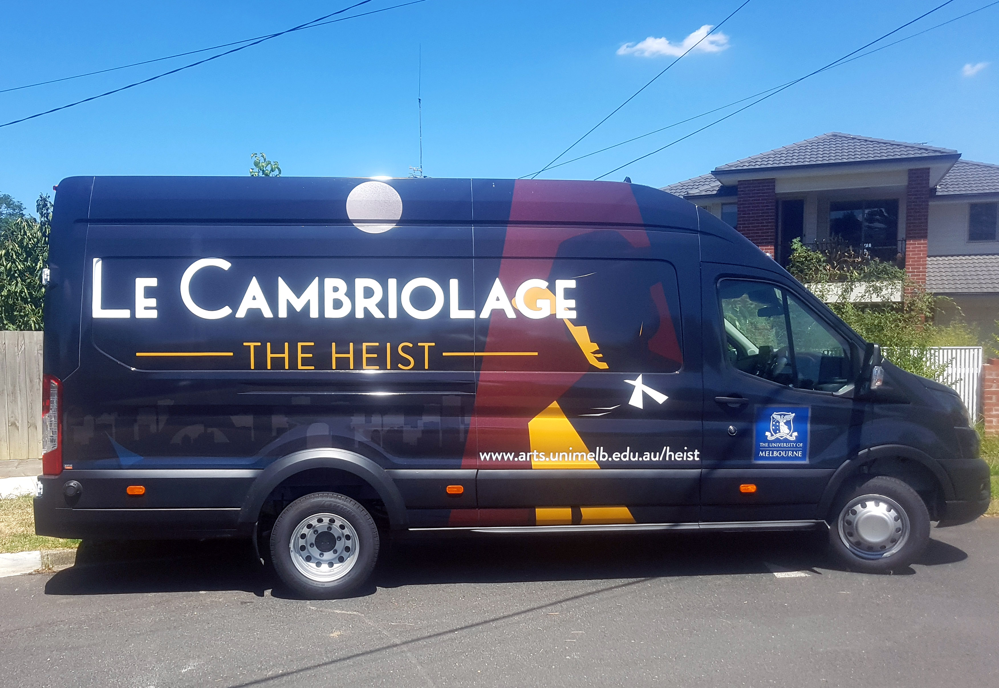
The van component of the puzzle started out as your typical while, long wheelbase, high ceiling Ford transit van… the sort of thing traffickers or organ harvesters would drive around picking up victims in.
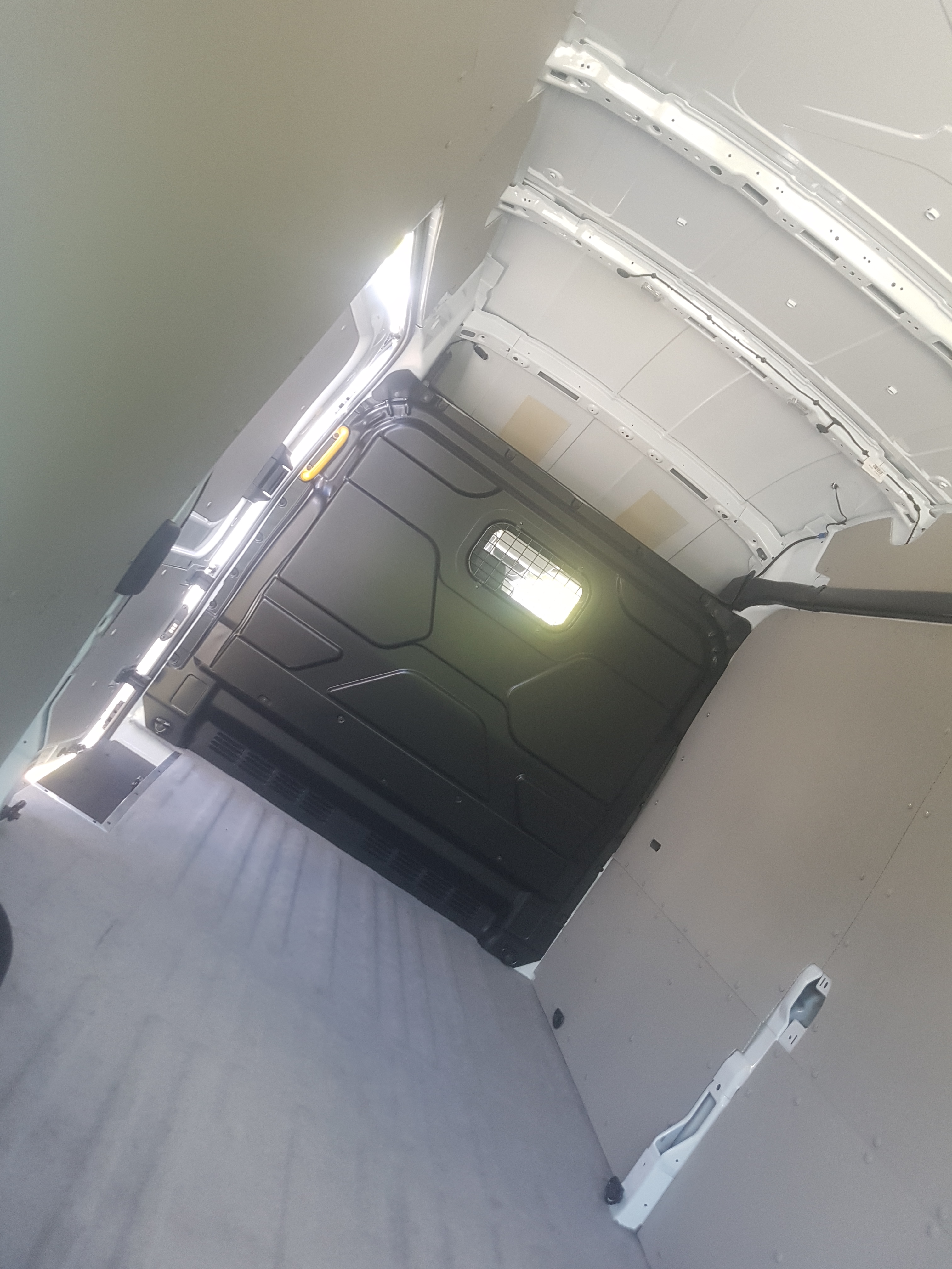
Inside was your average Ford quality van interior… durable plastic wall cladding with zero tiedown points, and easy to clean felt carpet… exactly the hardy materials that you want in the back of a work van.
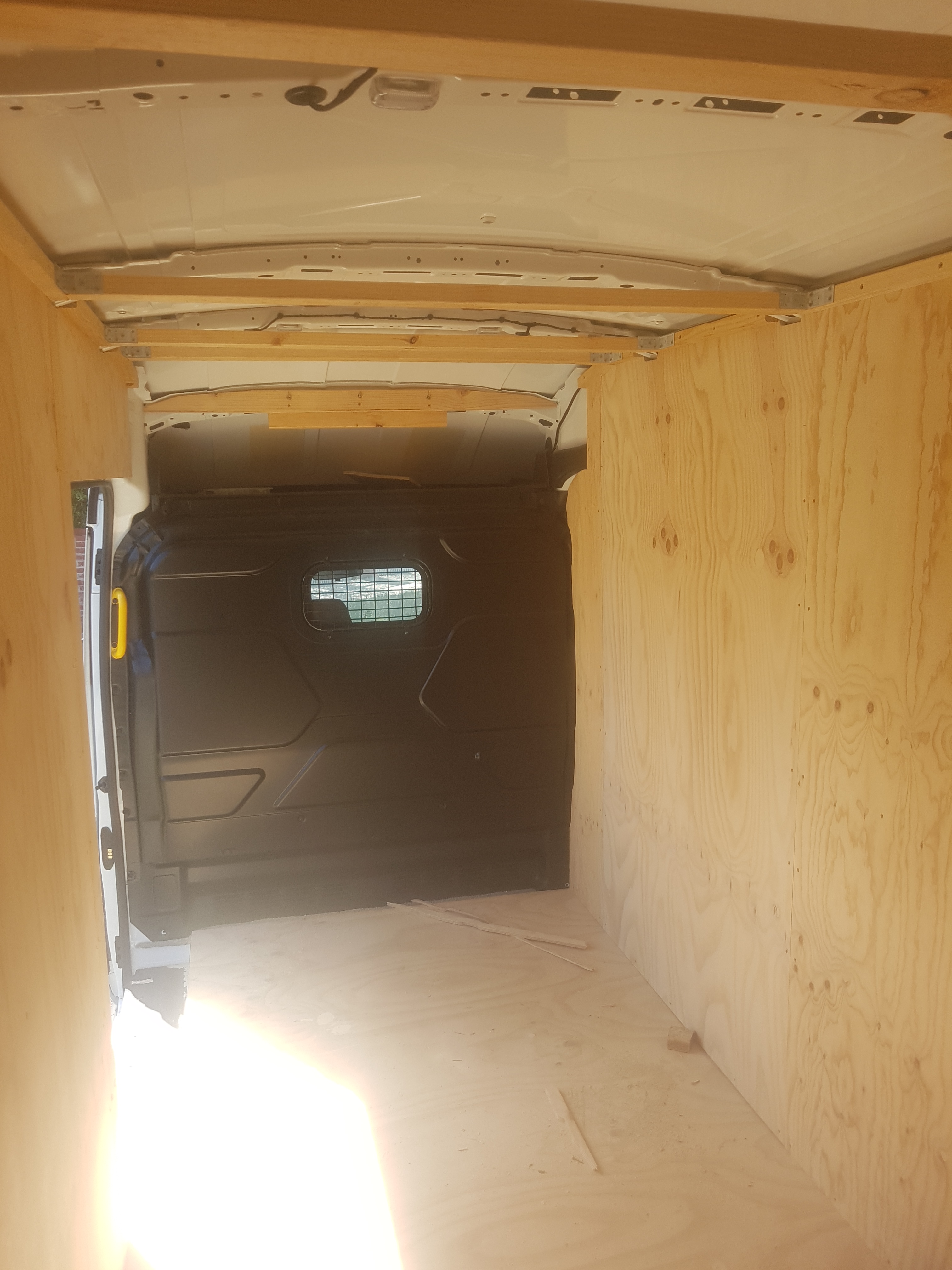
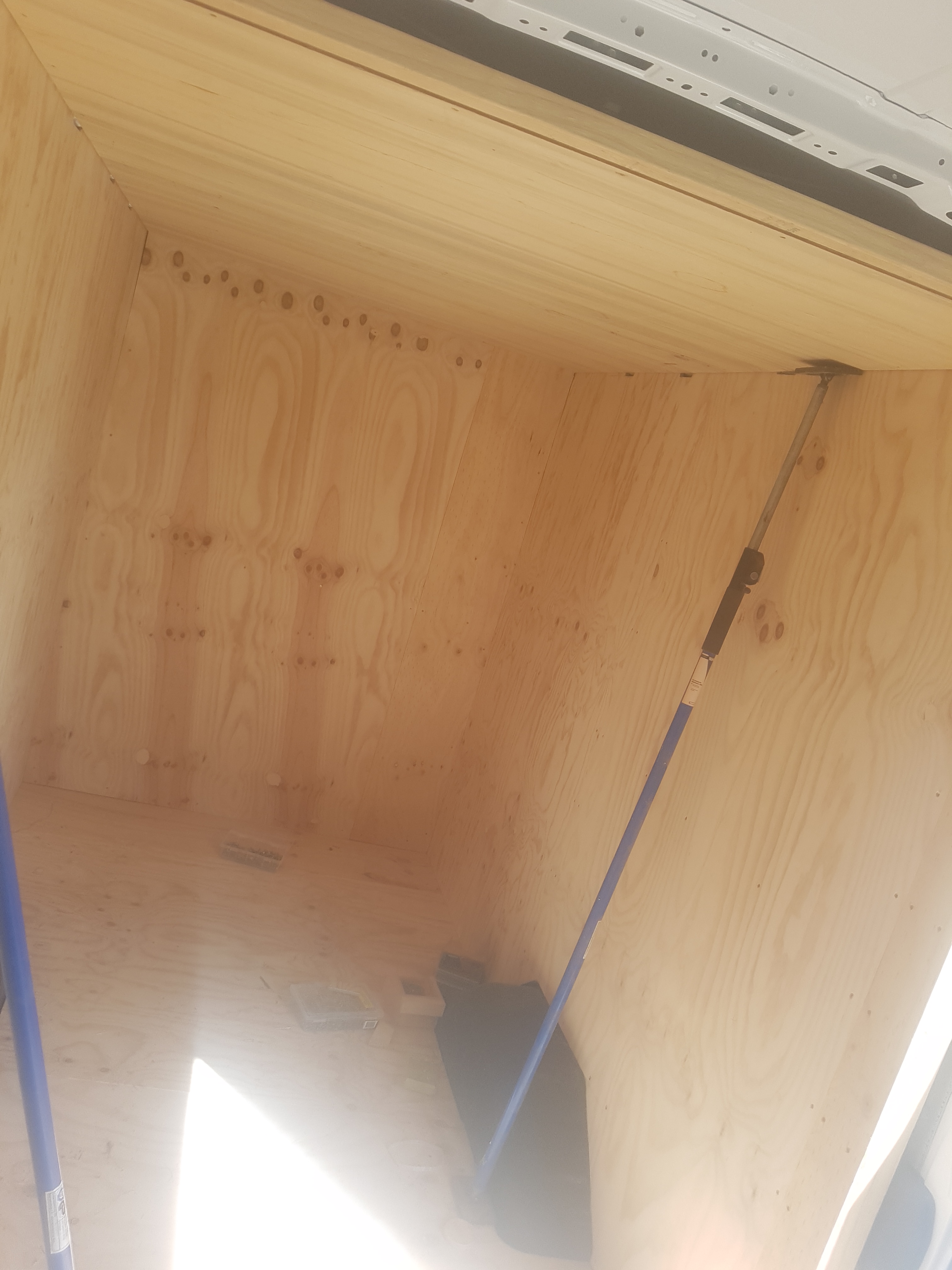
However with some pine studs, and plywood, the van was made into something usable, and in the scheme of thing, it didn’t actually weigh very much, probably 9 complete sheets worth of plywood and half a dozen studs. The roof was just 3mm ply as I’m not insane.
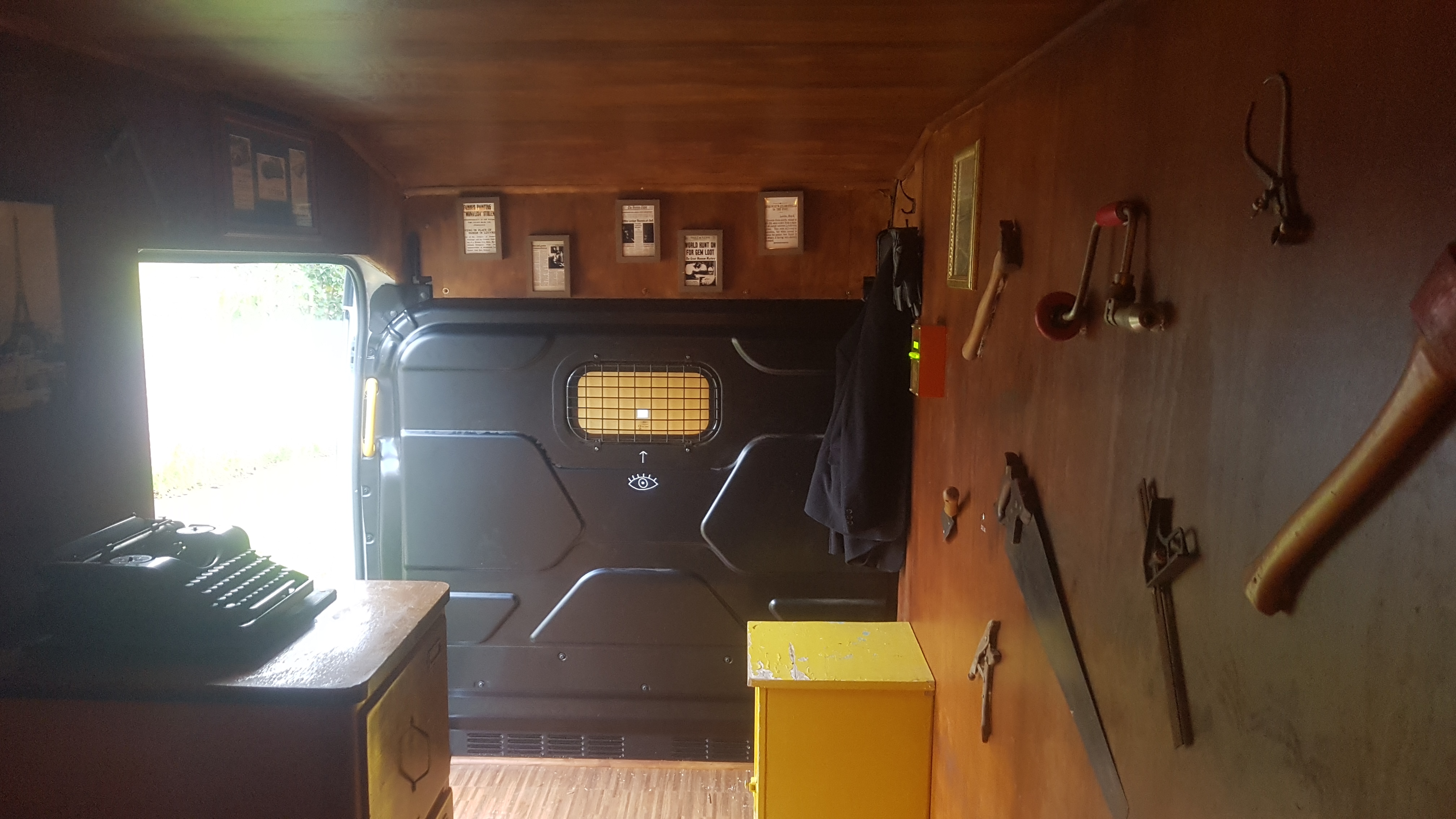
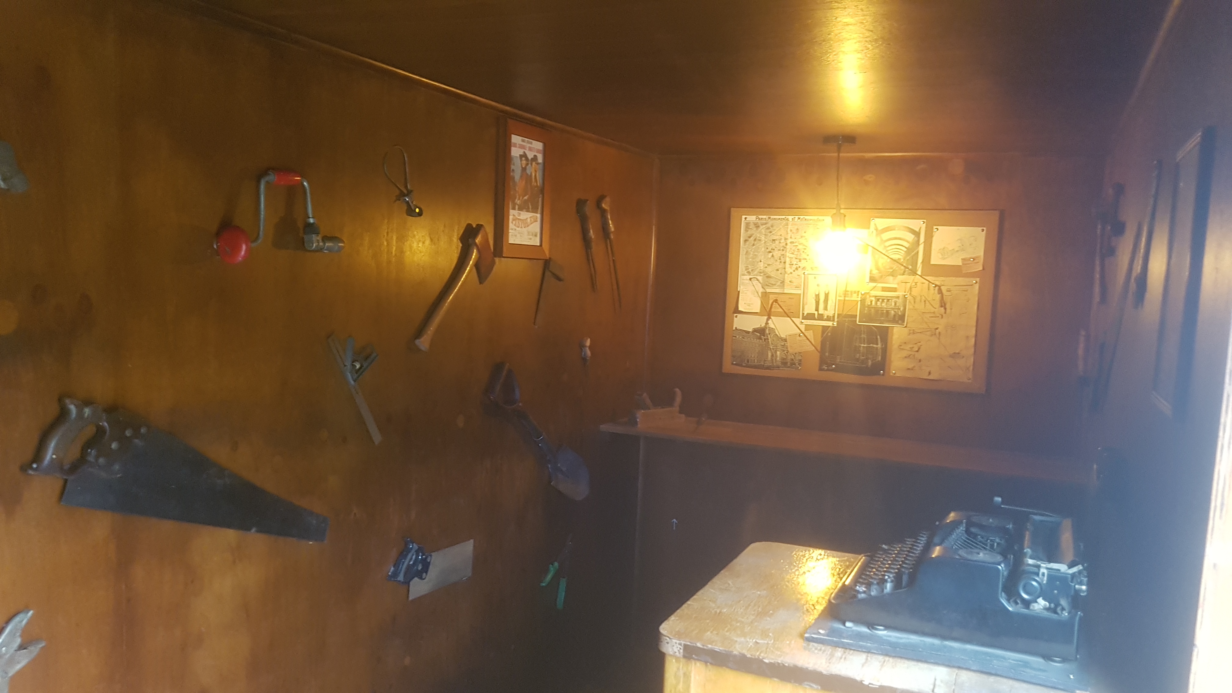
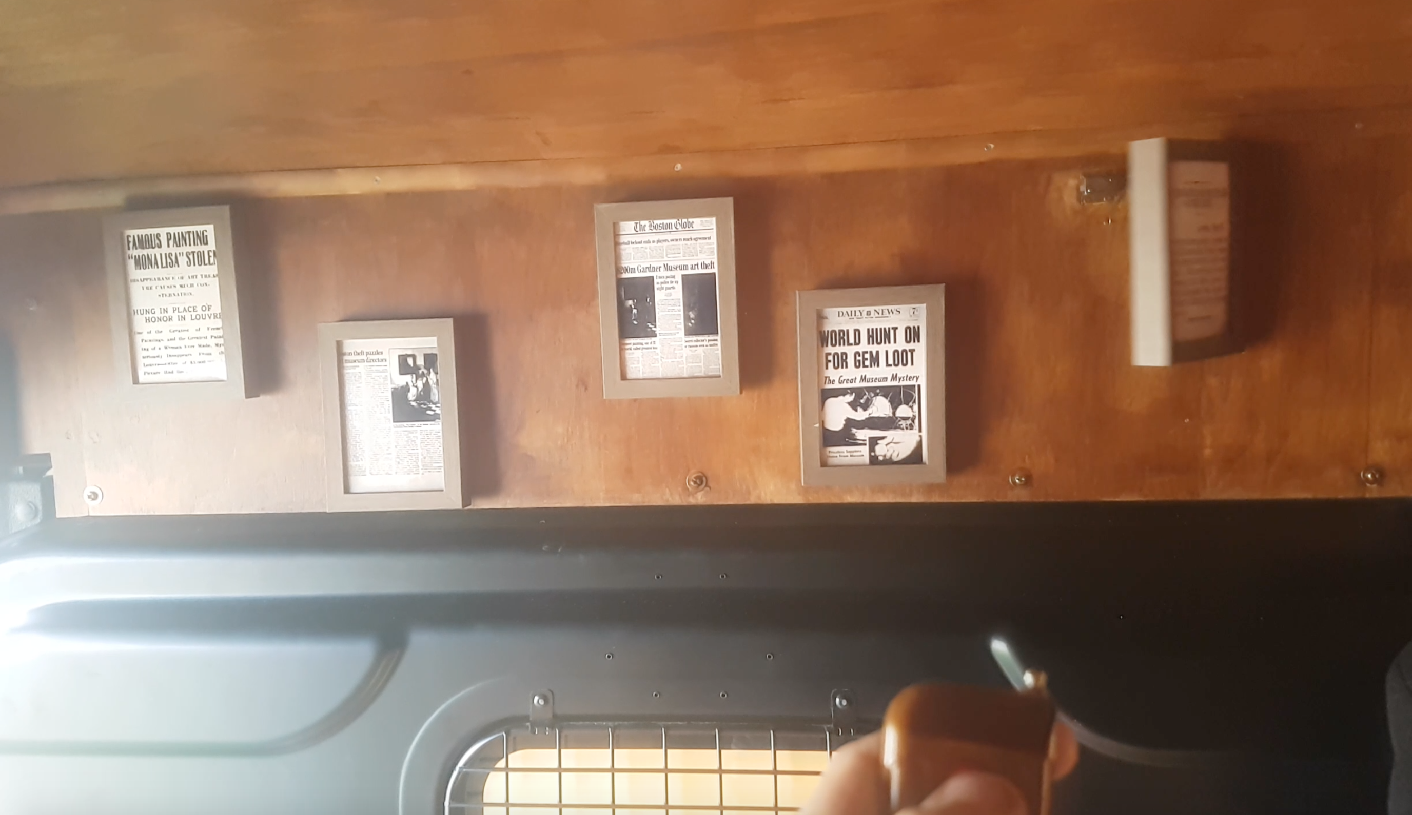
The van was then stained dark, given a vinyl floor, and fitted out in the most creepy way possible, with vintage tools, relics, and posters. All of which were heavily secured to the walls to stop kids ripping them off and beating/stabbing each other with them.
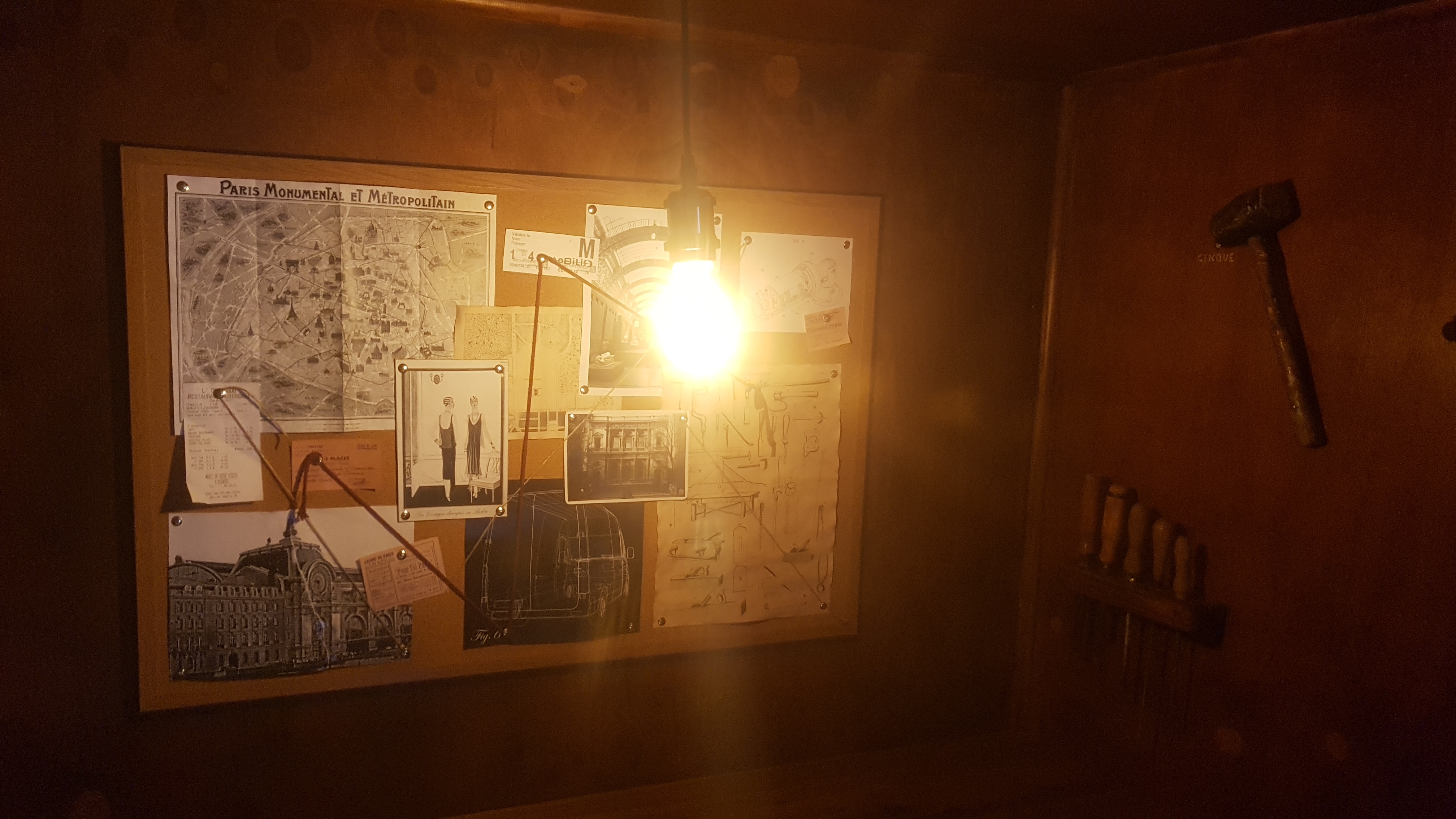
The pin board at the back was for the peephole puzzle, and as such needed a nice creepy light bulb to illuminate it once the van doors were opened.
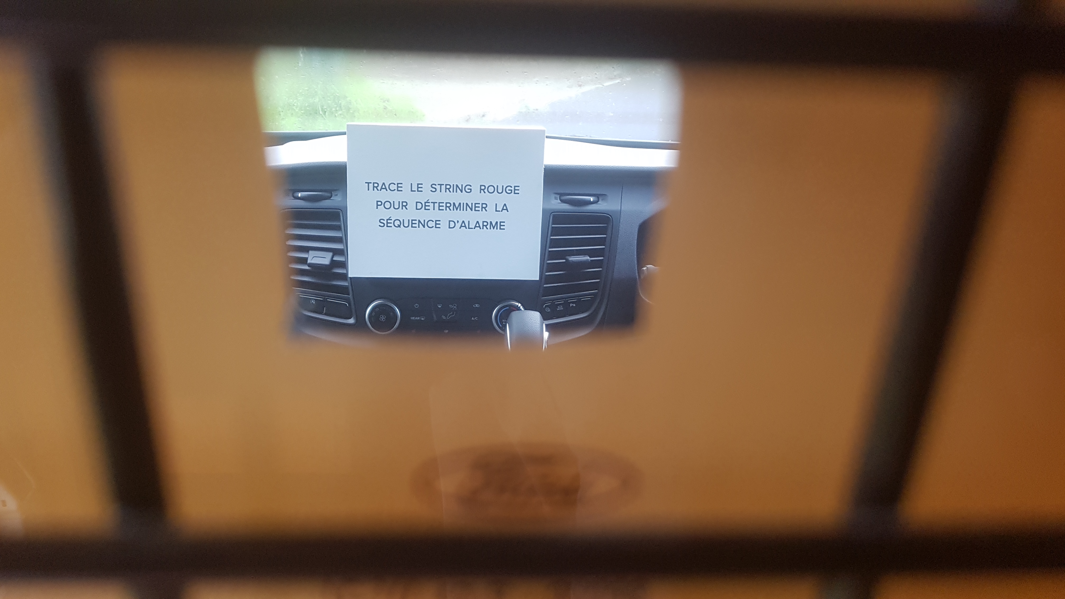
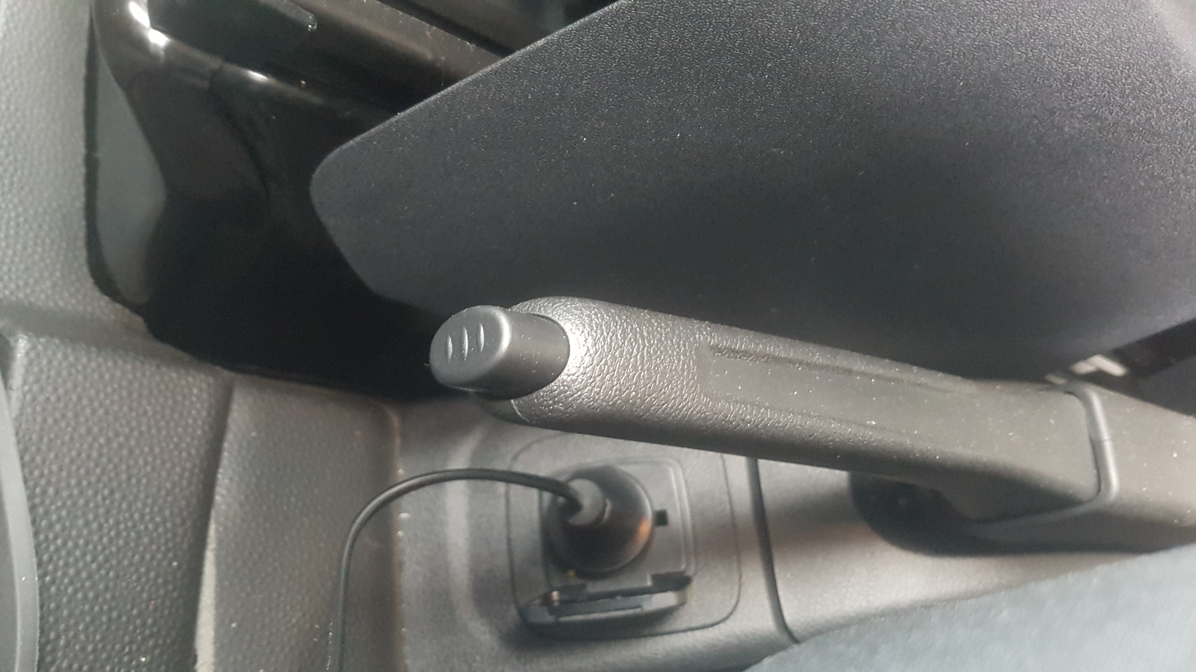
A peephole through into the van cabin would reveal the sequence of buttons to press in order to deactivate the alarm in the van.
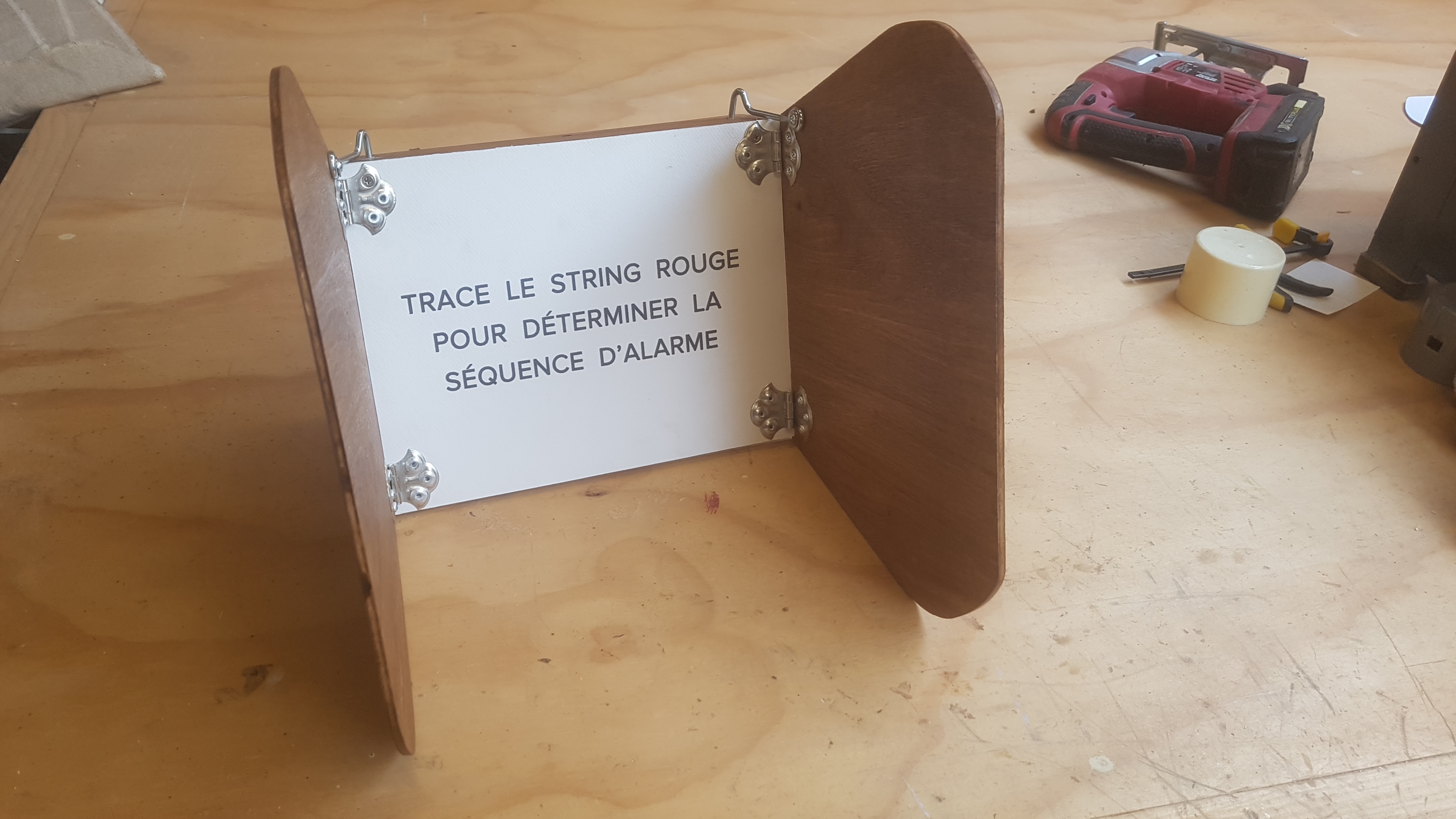
This little contraption would just sit over the console in the van cabin to reveal the peephole clue, it had little hinged blinkers on the sides to stop it being read through the windows.
The alarm was the main puzzle in the van, it has a timer, and makes the whole thing a race against time… except that it doesn’t as the timer deliberately slows down as time progresses to give the illusion of time running out. It’s coupled to an MP3 playback module that prompts the students on how to deactivate the alarm after failed button inputs, or certain time intervals. As each button is pressed in the correct sequence, the LED’s on the front change from red to green.
I decided to CNC the front panel out of solid brass… I have no idea why i decided to make life so difficult on myself, but with the right cut depth and speed it actually worked really well, and looks steampunk.
Brass is handy for soldering mounting points.
The speaker and LCD screen module happily mounted into their new home… now it’s just time for the spaghetti wiring.
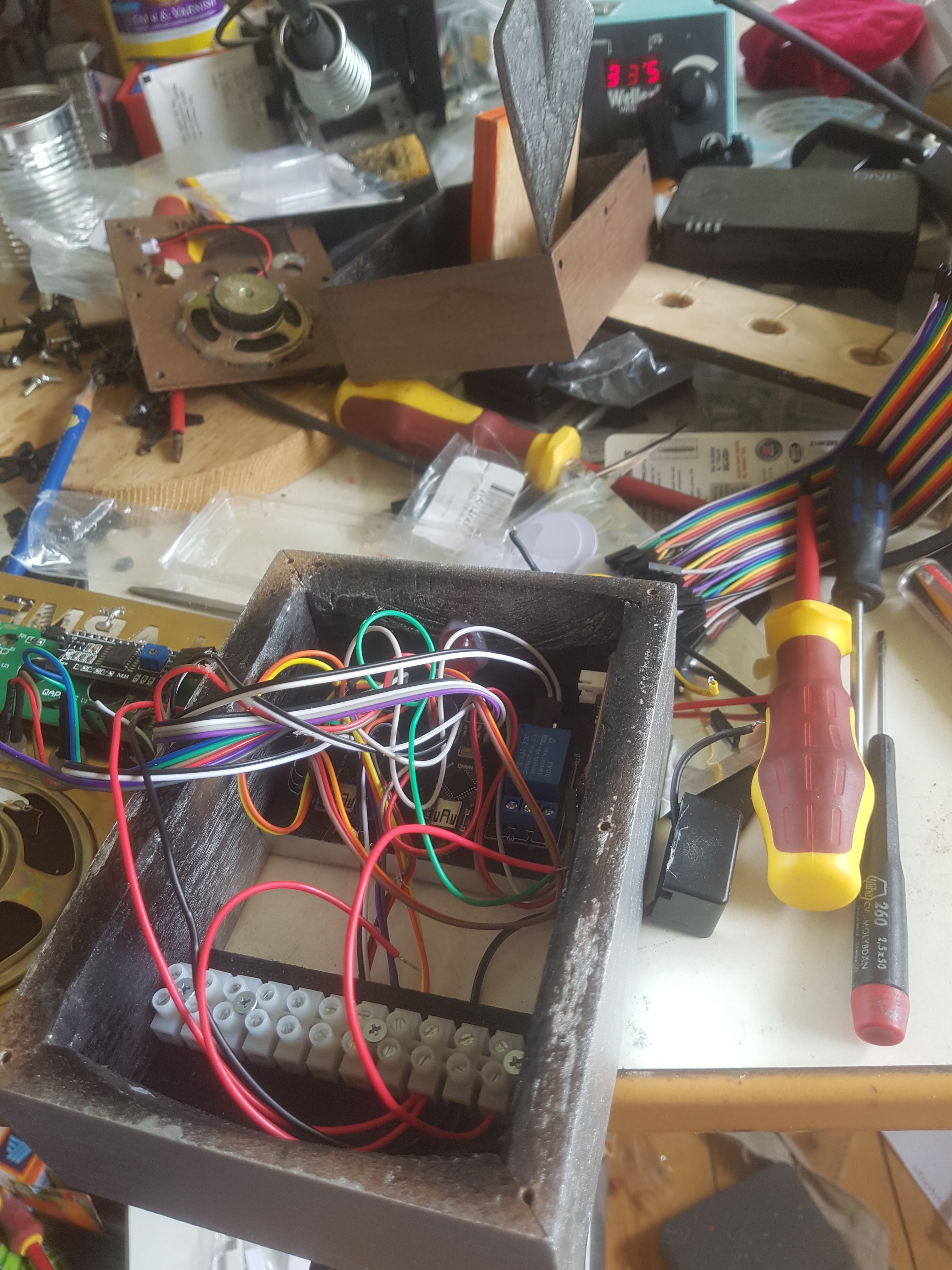
It looks worse than it is, it’s just an arduino nano driving 4 bicolour LEDs, a serial MP3 module, an i2C LCD screen, and a relay. I put a flashing red LED behind the cutaway alarm text to give a nice visual effect.
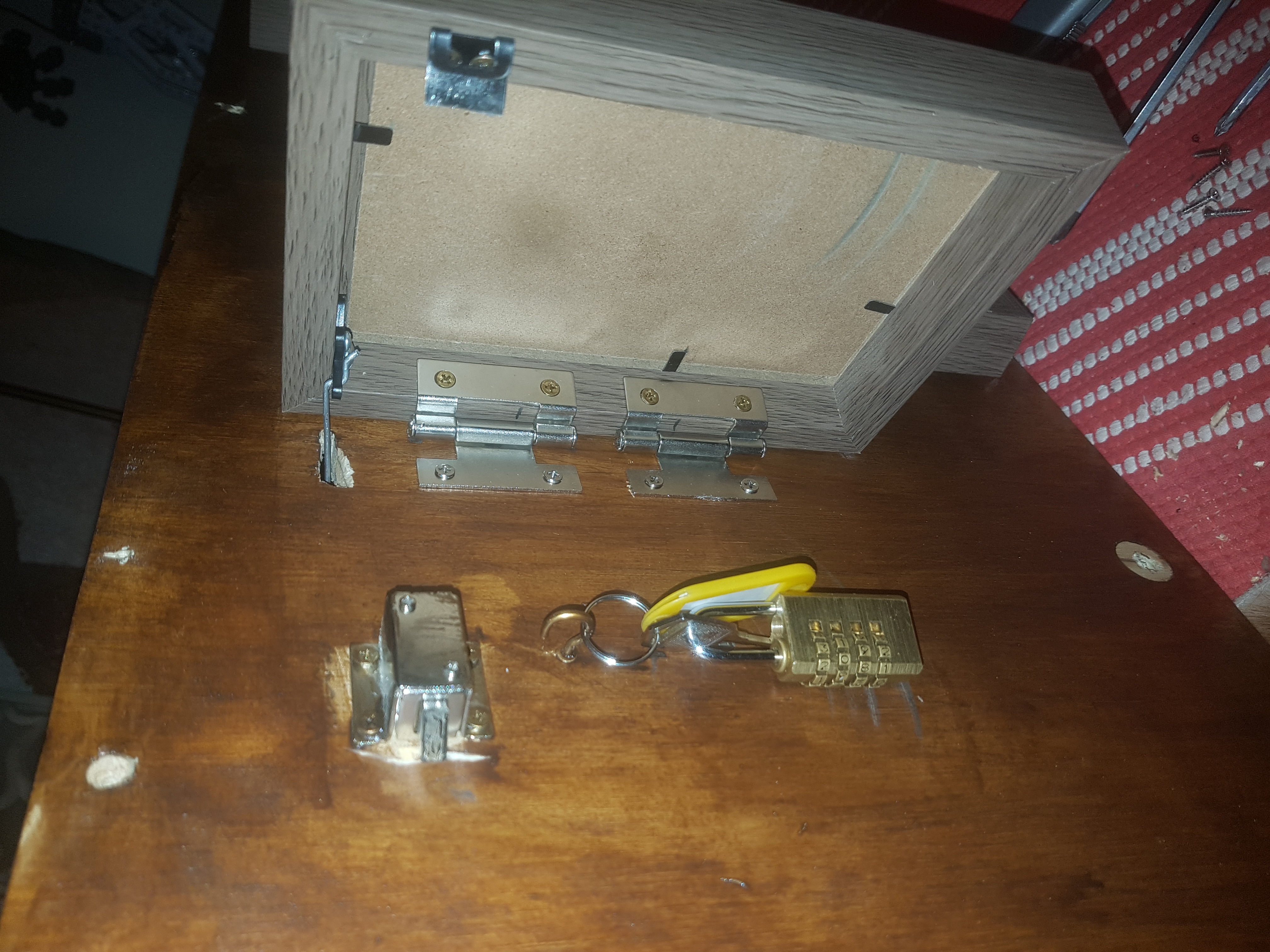
Once the alarm is deactivated the students could push the remote control button that they were given, which reveals a key tethered to a lock hidden behind a hinged picture frame.
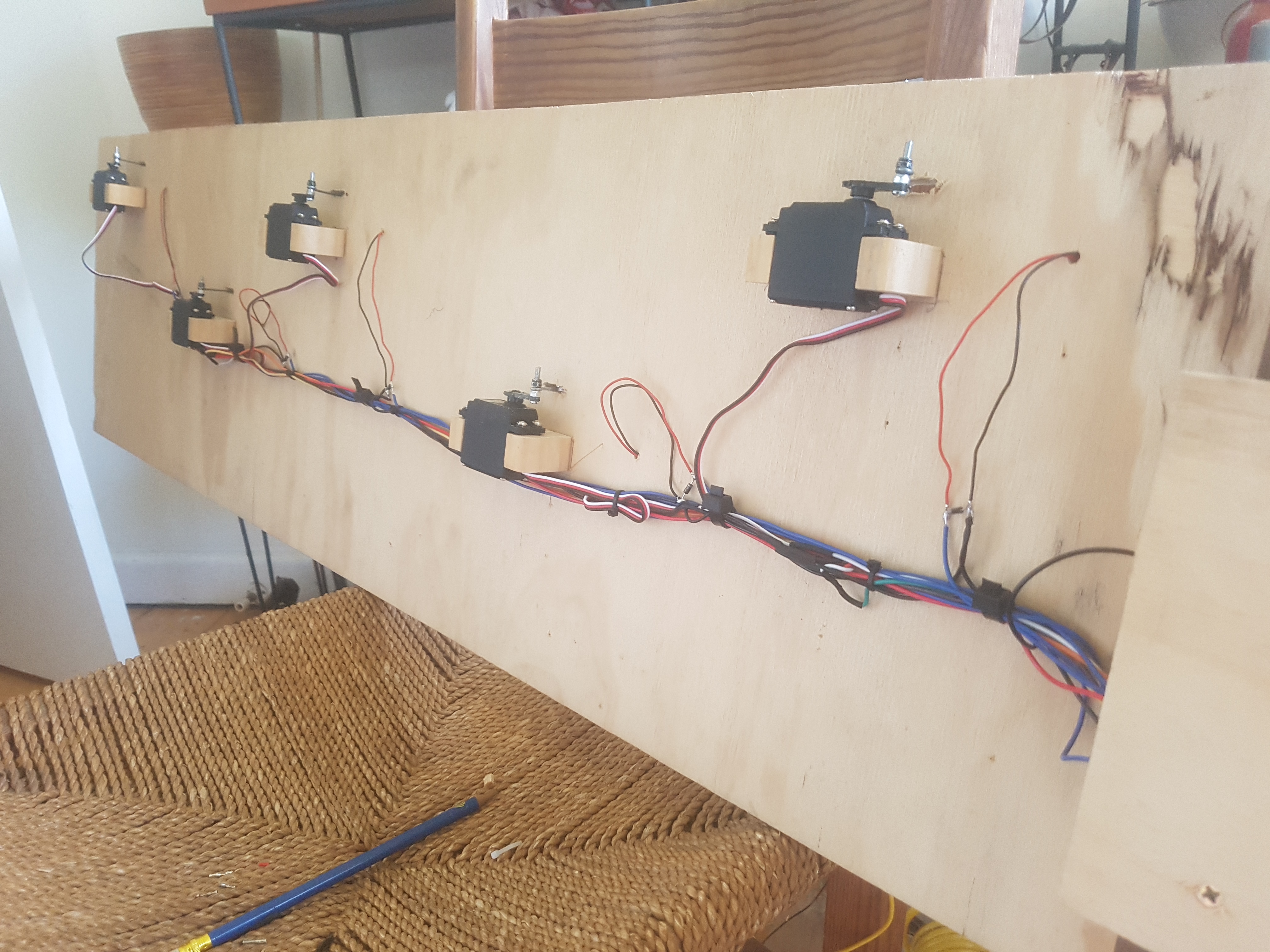
This was done using servos, magnetic latches, and some rolling code remote modules. A little arduino and a relay board handled the unlatching and servo control side of things.
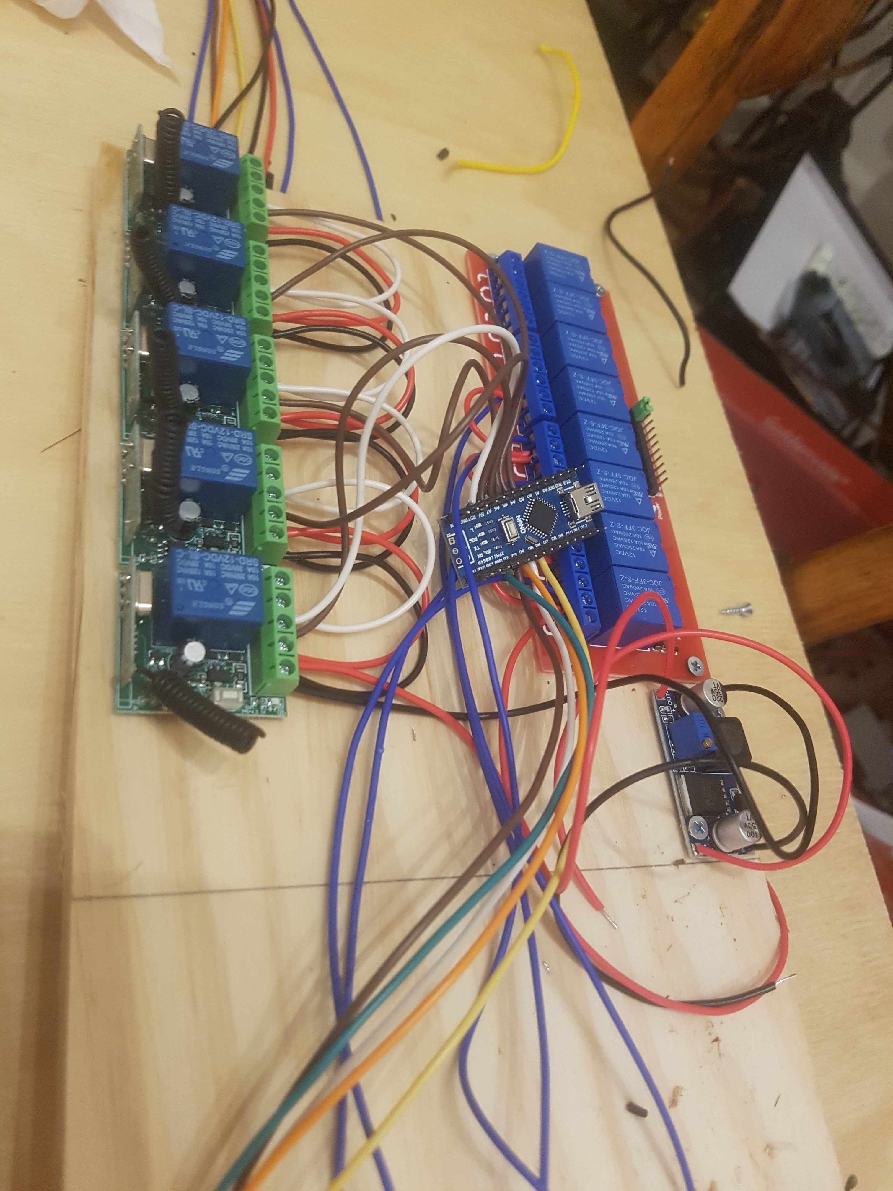
The whole thing is powered by a buck converter to keep everything happy voltage, wise with the servos and the arduinio only wanting 5 volts… the remote modules and relay boards have their own regulators and are happy to be fed with 14-12 volts no problems.
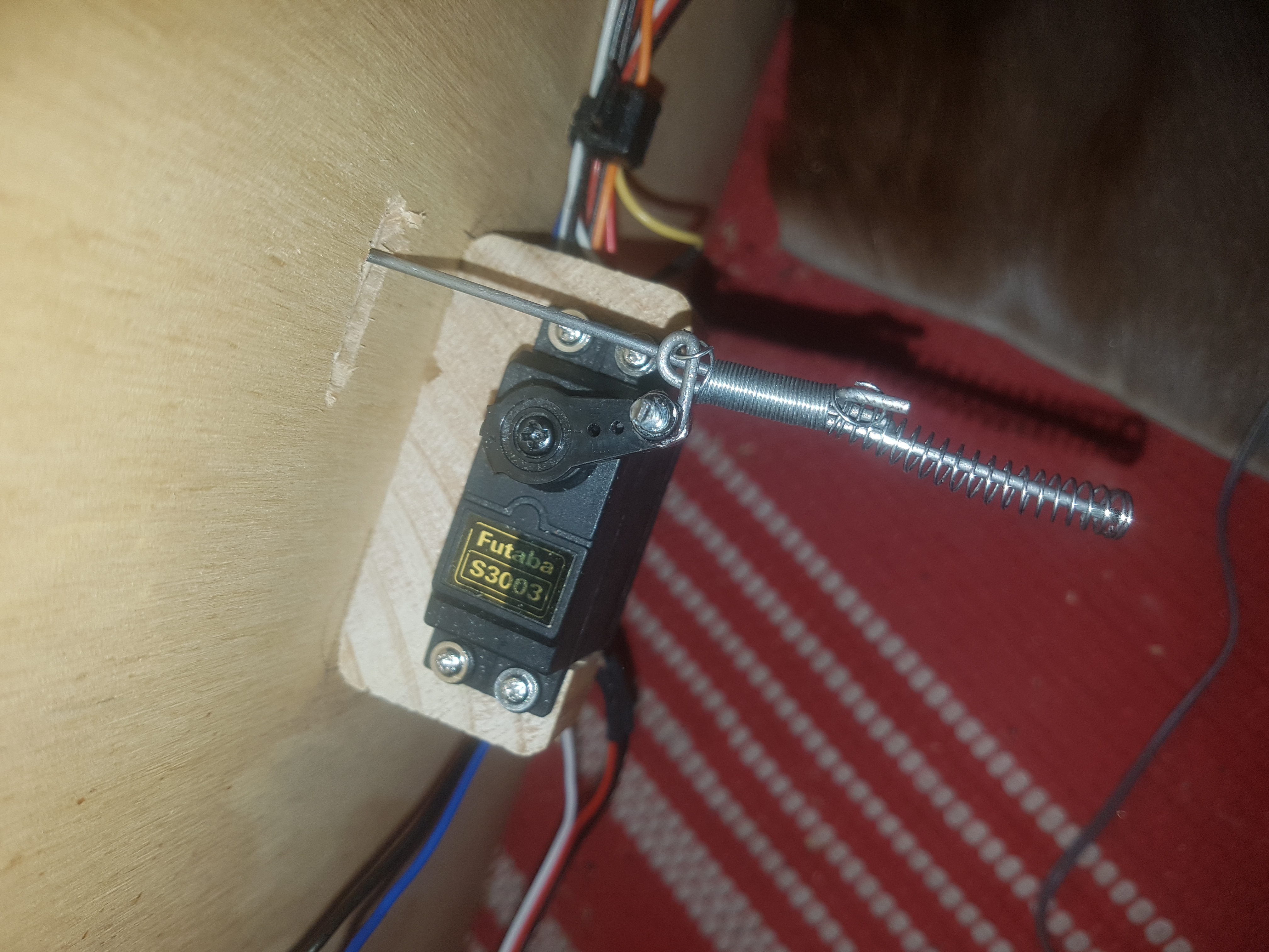
To stop the servos being destroyed by kids slamming an open door, I designed a spring loaded control rod, which actually works frighteningly well.
Here you can see the hinges, servo linkage, and electronic latch mechanism all working as intended.
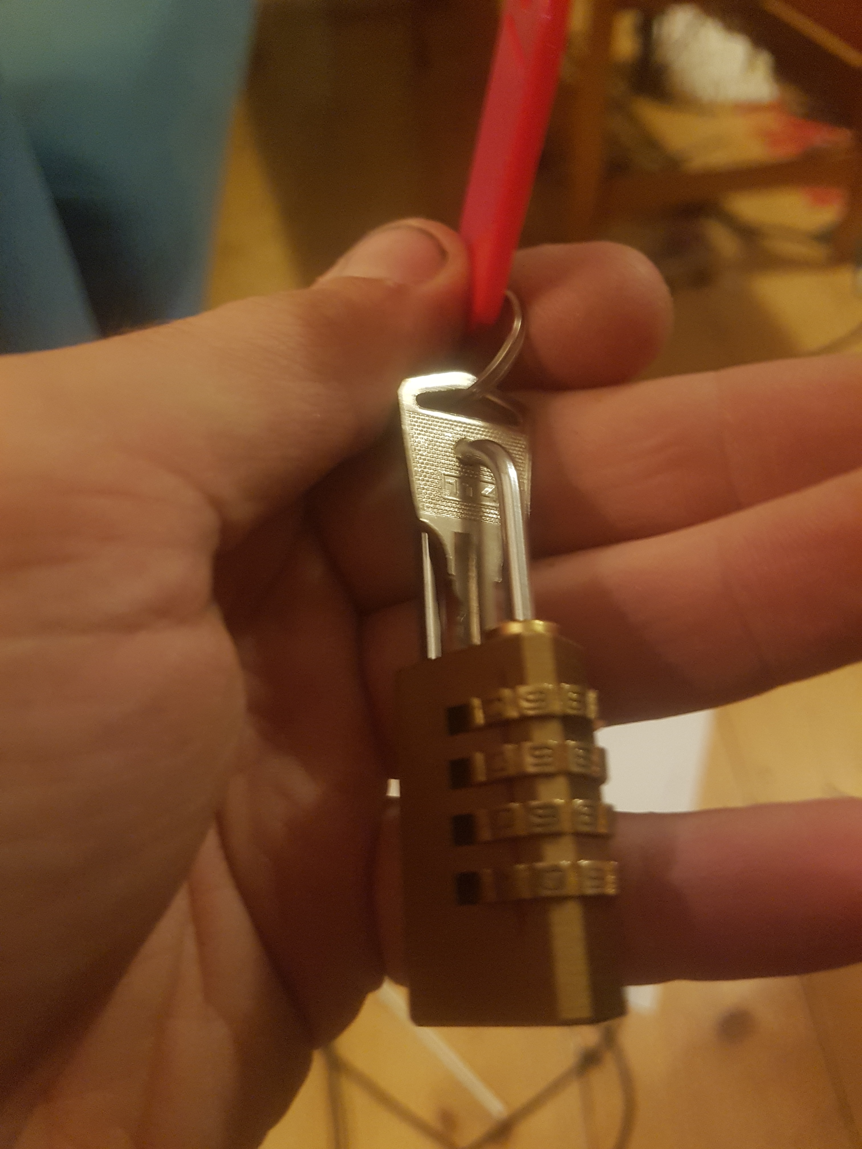
By drilling a shallow hole into the top of the brass combination lock, and putting a hole through the key, I was able have the key locked behind a combination.
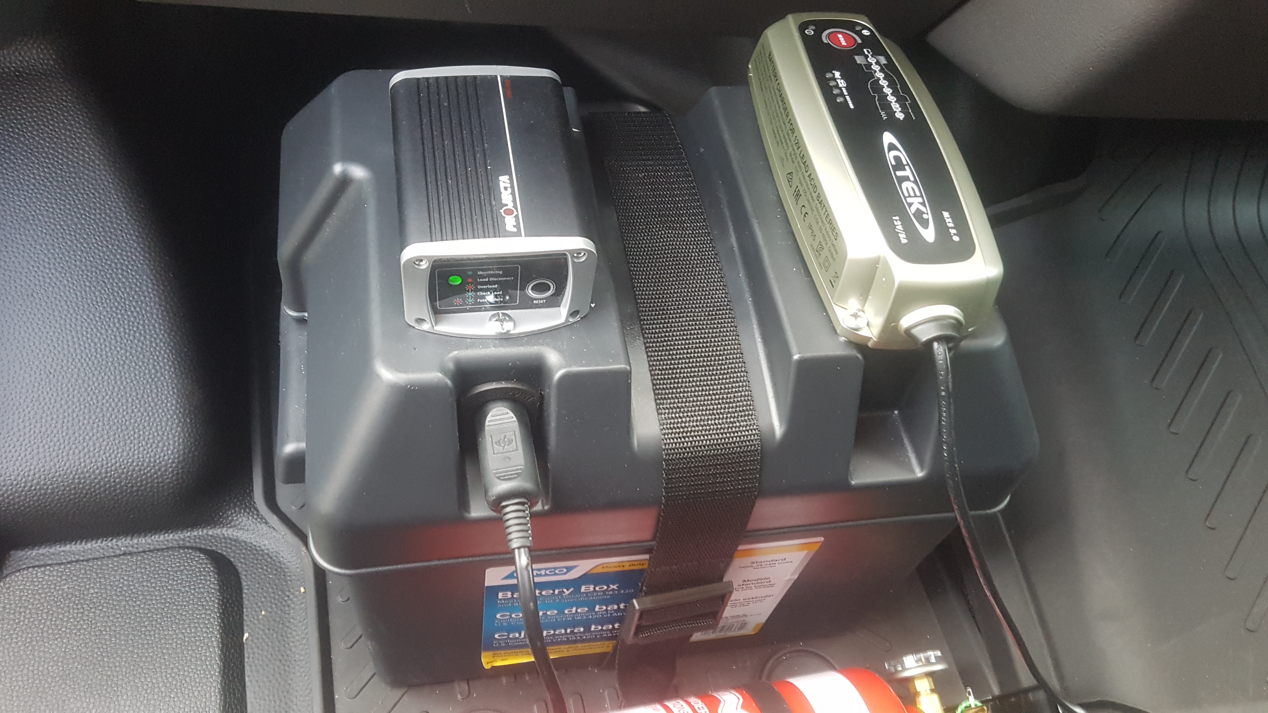
The whole van part of is powered by a 12 volt SLA battery in a battery box, charger, and low voltage cutout.
The transit van has it’s own inverter which is powered up when the ignition is on, so I took advantage of this to charge the battery box with when the van is driving.
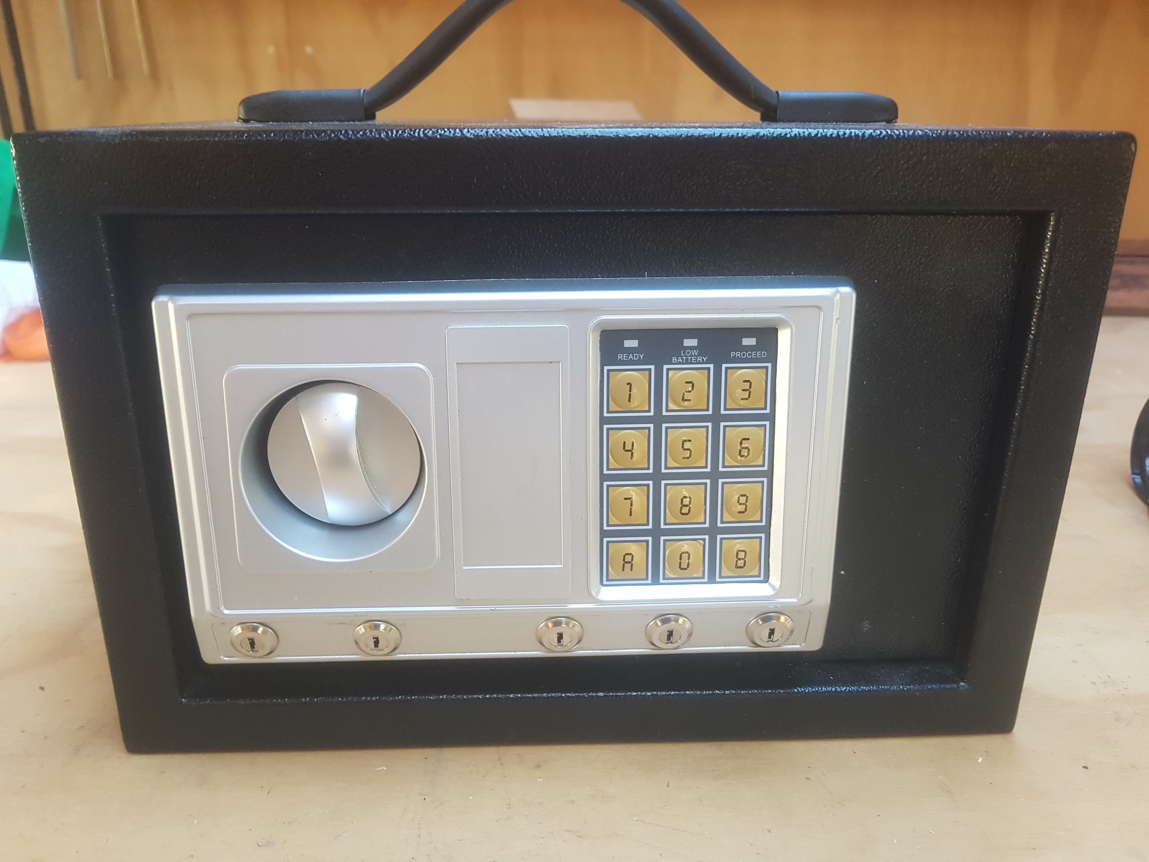
The safe has a combination and a correct colour order for the keys to work, when opened it plays music and illuminates, this again is just done with an arduino nano, and MP3 module, and a micro-switch to detect when the door is open.
I feel that the videos explain the causality of the rooms rather well. It has been running consistently for two years with only minor repairs and mishaps, which is quite good considering how destructive kids can be.