WANHAO Duplicator i3 Z-Axis extension Decided to extend the Z axis on my Wanhao i3 printer as it was wanting to print some rather tall teardrop lampshades.
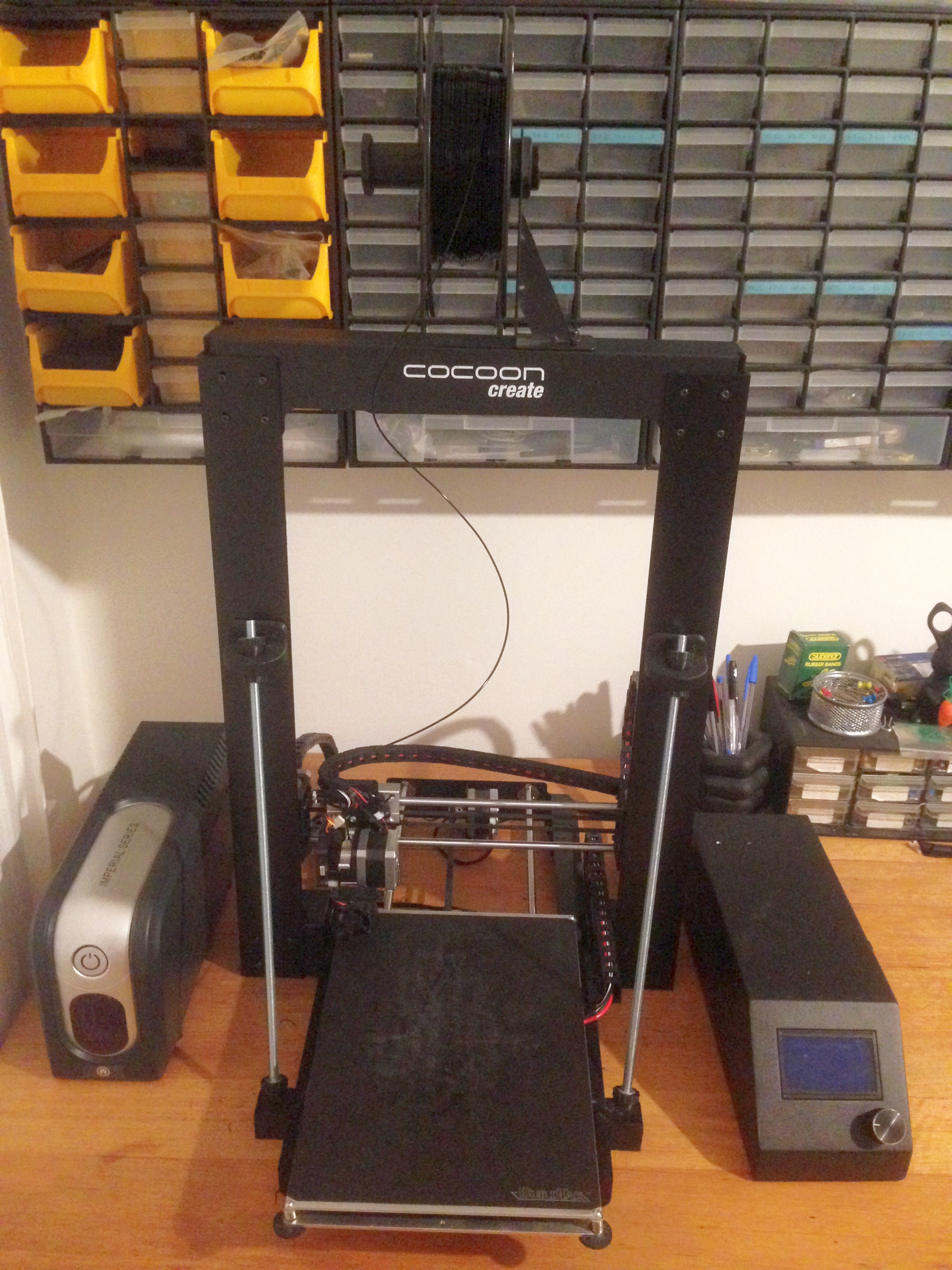
The whole process is very simple and only requires about $40 worth of parts, you will need:
- 1.5 meters of 60 x 3mm equal mill aluminium angle. This can be found pretty readily at window manufacturers and good hardware stores.
- Two T8 8mm screw length 500mm picth 2mm lead 8mm trapezoidal screw with 1pcs brass copper nut
- Two 8mm L600mm linear shaft OD 8mm x 600mm Cylinder Liner Rail Linear Shaft Optical Axis cnc parts
- You will also need a about 30 M3 x 8mm socket head screws
- A 2.5mm drill and an M3 tap (or if you can’t justify buying a tap just drill the holes out and use nuts from behind)*
- A 1.6mm (or 1.5mm if you ream the hole slightly) drill and an M2 tap*
The original cable chains are enclosed and require the wire be fed through them which would mean removing the connectors from the end of the wires.
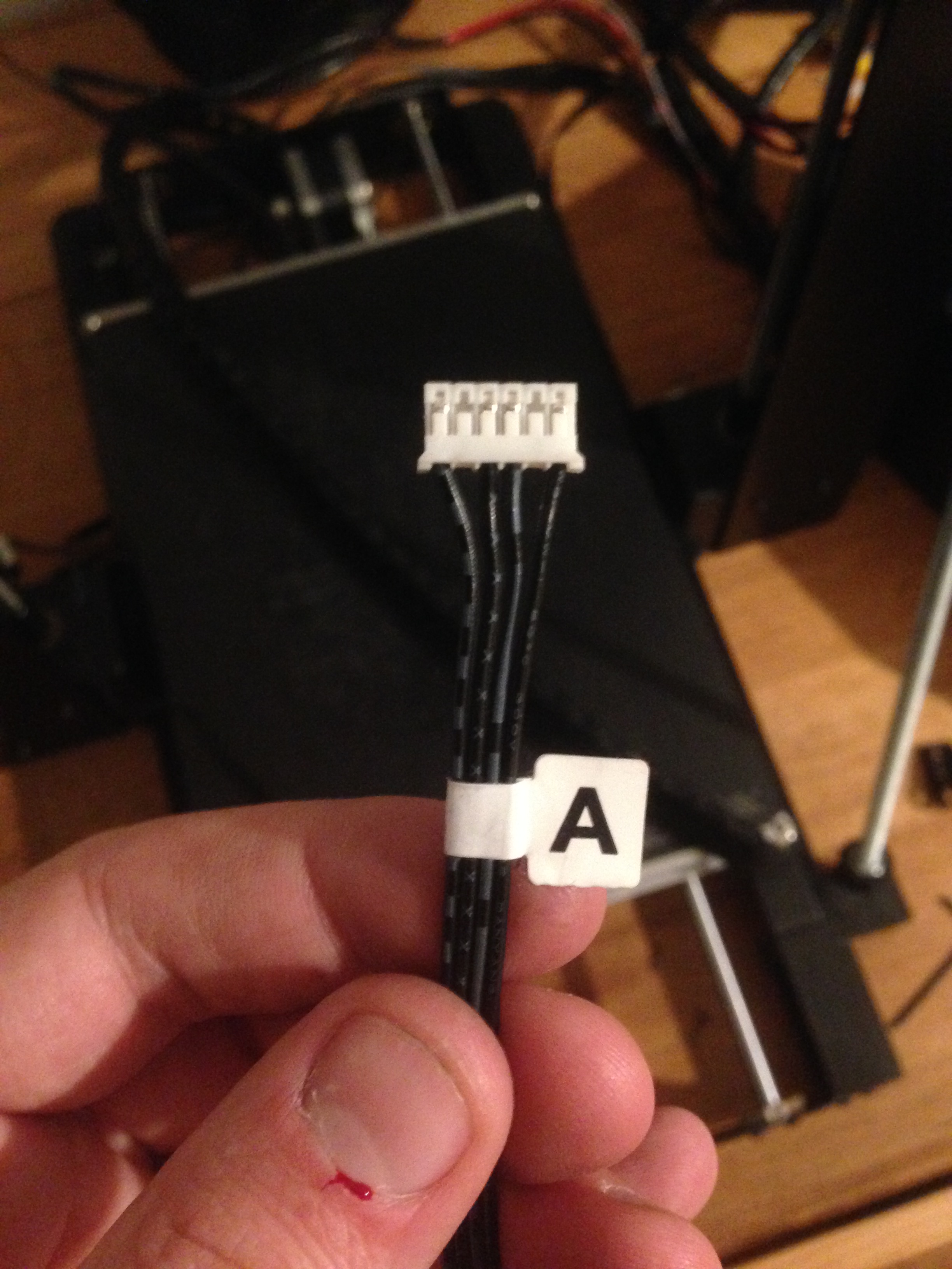
So I designed some open top extensions to fit into the original Z axis cable chain, this negates the need to disassemble the loom connectors. I fitted one of the open topped extensions between each original so that there was no chance of the cables popping out, you will need 20 of these.
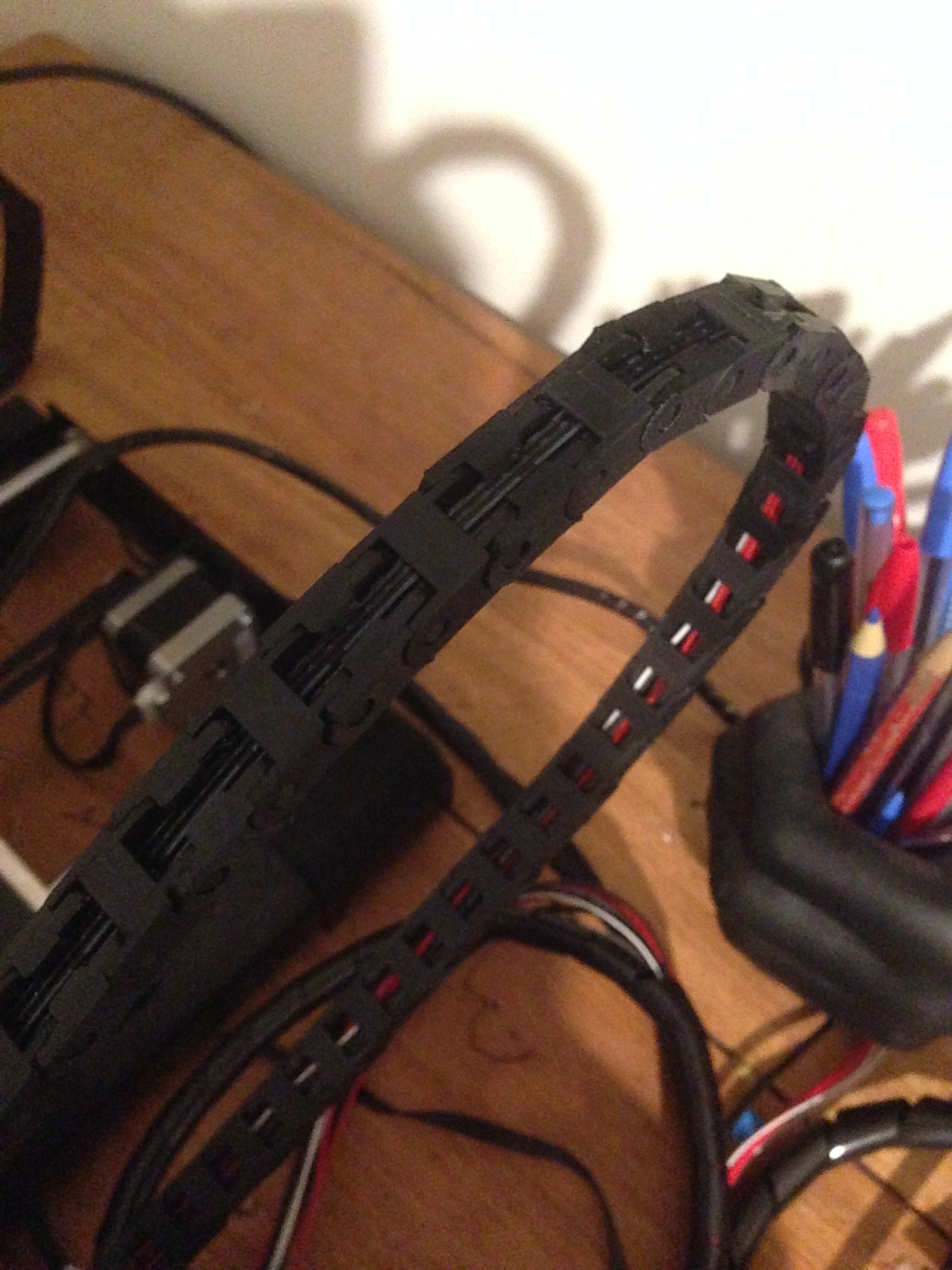
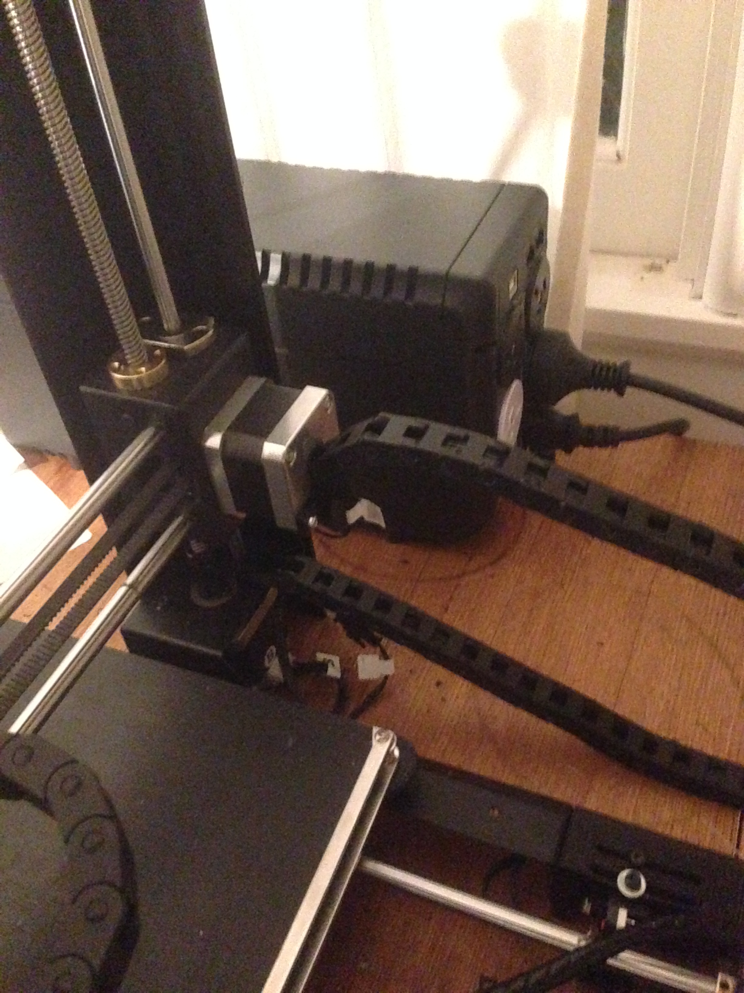
A second Z axis chain for the opposite side will also need to be printed, but this one can be enclosed as it is easy to remove the connector and feed the wire through. You will need to print 40 of these, a bottom mount and the stepper motor mount.
The manufacturing process is very simple and mostly requires cutting, measuring and drilling the aluminium angle.
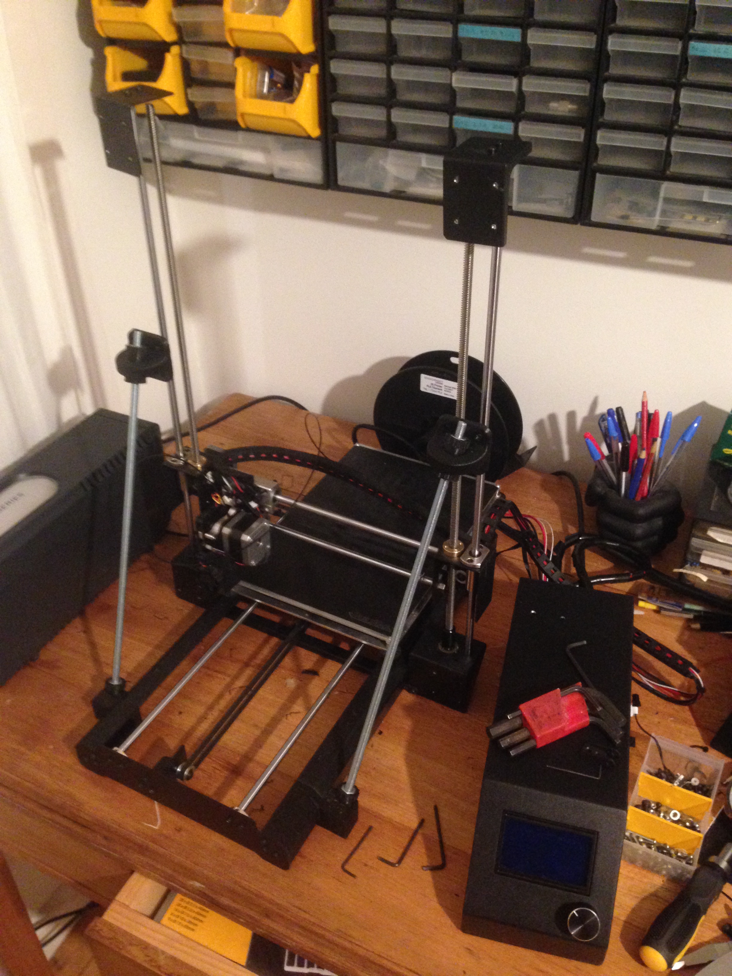
The first step is to measure your original feed-screw against the new longer feed screw. The difference in length between the two will determine how much longer than the originals to cut your aluminium angle. Simply add this difference in length to the length of your original steel uprights and cut the aluminium as squarely and consistently as you can.
Once you have two identically sized pieces of aluminium angle it’s time to drill holes. The easiest way is to make cardboard templates of the screw locations from the inside of your original uprights. It’s important to make and use the templates from the inside of the angle uprights in order to get an accurate measurement.
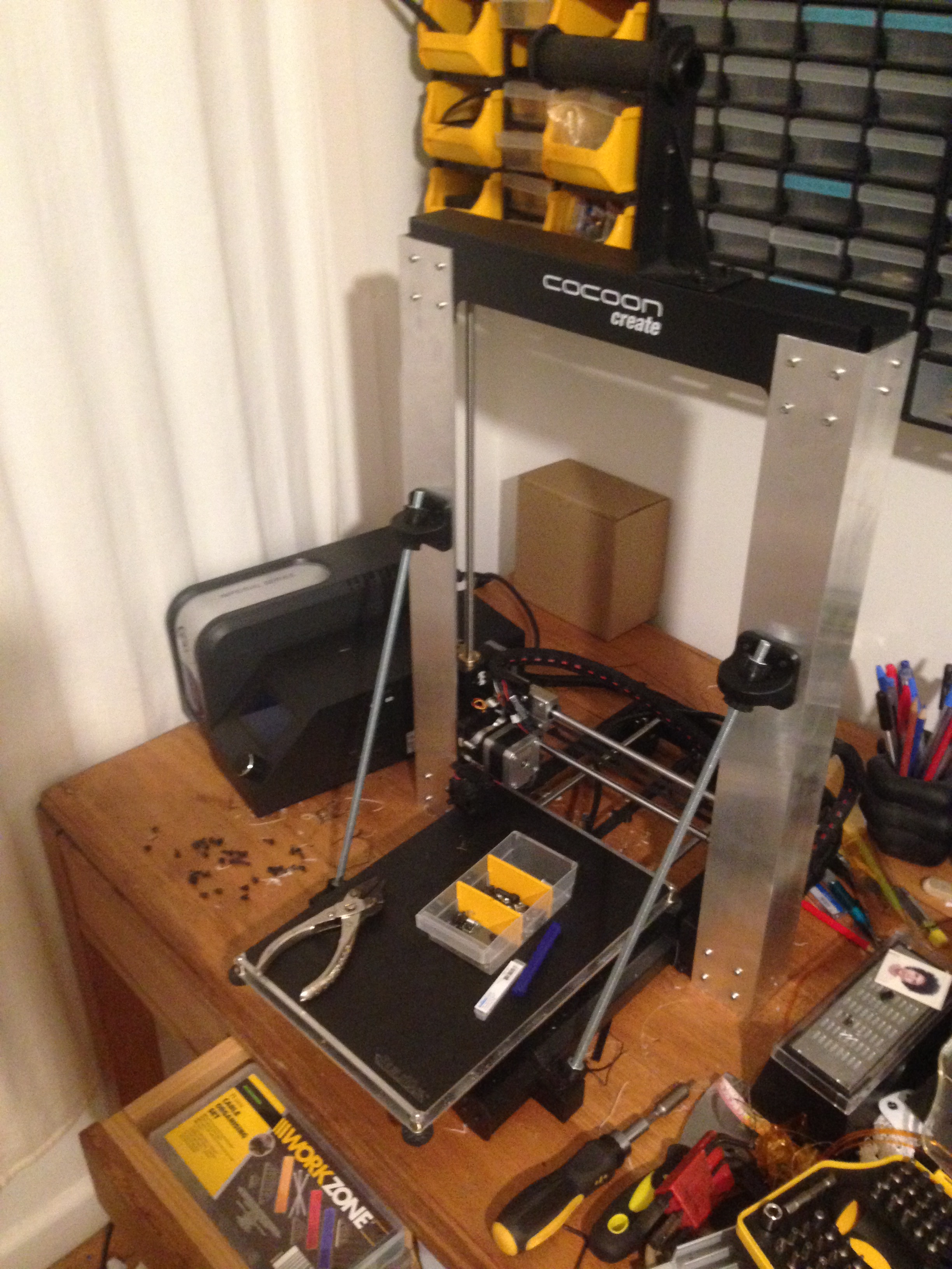
To get the elongated screw holes simply drill two 3mm holes side by side and angle the drill to join the two and clean away the waste.
Measure up from the bottom to drill the Z-axis support holes, being sure to use the 2.5mm drill then cutting a thread by running the M3 tap through them. The Z axis brace holes will need to be drilled at the same height as the top of the old upright holes.
The final drilling and tapping is for the Z-axis limit switch, simply make a template and measure up from the bottom, then drill the hole with the 1.5 or 1.6 mm drill and cut a thread with the M2 tap.
It’s now simply a matter of cutting the bearing rods and reassembling the printer in the same way that you disassembled it. To cut the rod, measure your old bearing rod agains your old feed screw. You then add this distance to the length of your new feed screw and use this to mark and cut your new bearing rod.
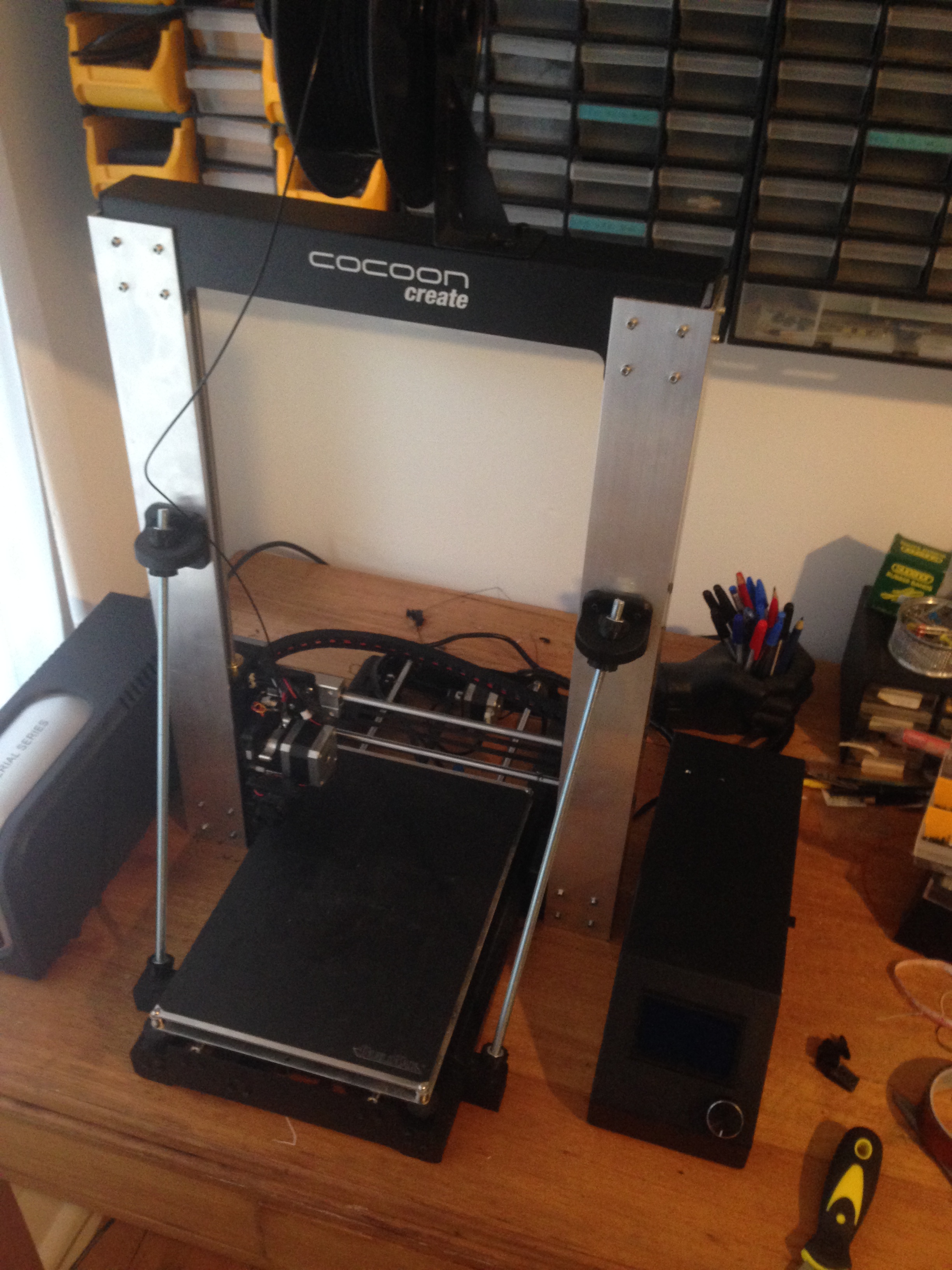
To get the printer to recognise the extra length it’s as simple as going into Repetier and changing the EEPROM values.
After doing this I realised that it would be a piece of cake to give the heater bed cable the same treatment as it was infuriatingly cumbersome and easily snagged. I simply printed another 22 closed cable chain pieces, designed a bottom bracket that clamps onto the steel frame, and a top bracket that mounts to the bottom of the build plate carrier so as to keep things well clear of the heat.
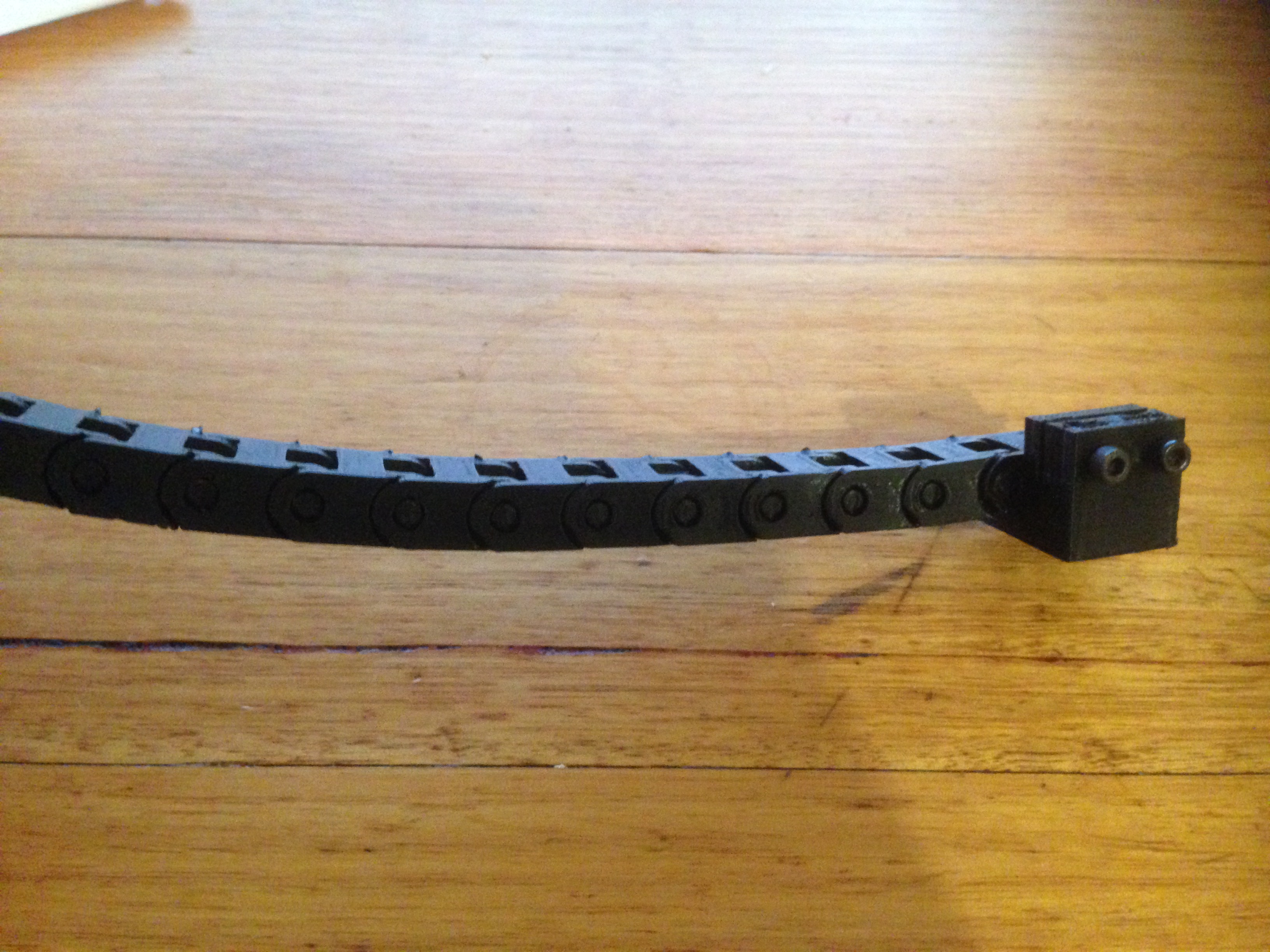
The bottom bracket slides over the frame and is held in place with two M3 bolts a which tighten into captive M3 nuts. If you have trouble getting the nuts into groove, heating them with a hot soldering iron will do the trick.
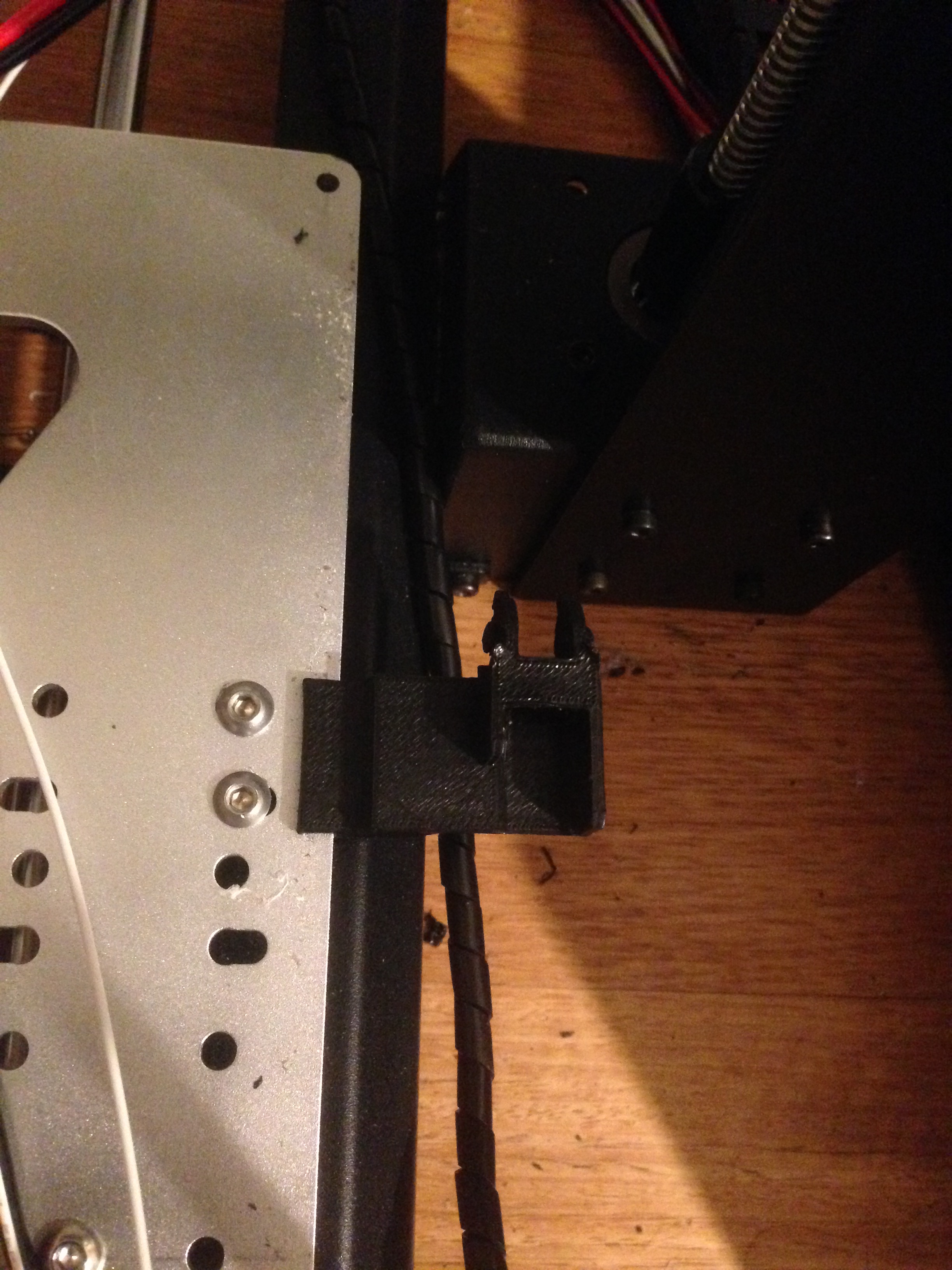

The top bracket just bolts through the carrier plate using M4 bolts into captive nuts at the bottom of the bracket, again a little heat with the soldering iron helps guide and lock the captive nuts in place. Then just thread your cable through the chain and wire things back the way they were. I’m using a 20x30mm build plate, but this cable chain should work just as well on the 20x20mm beds, it just might require a few less links, so experiment before bolting things into place.
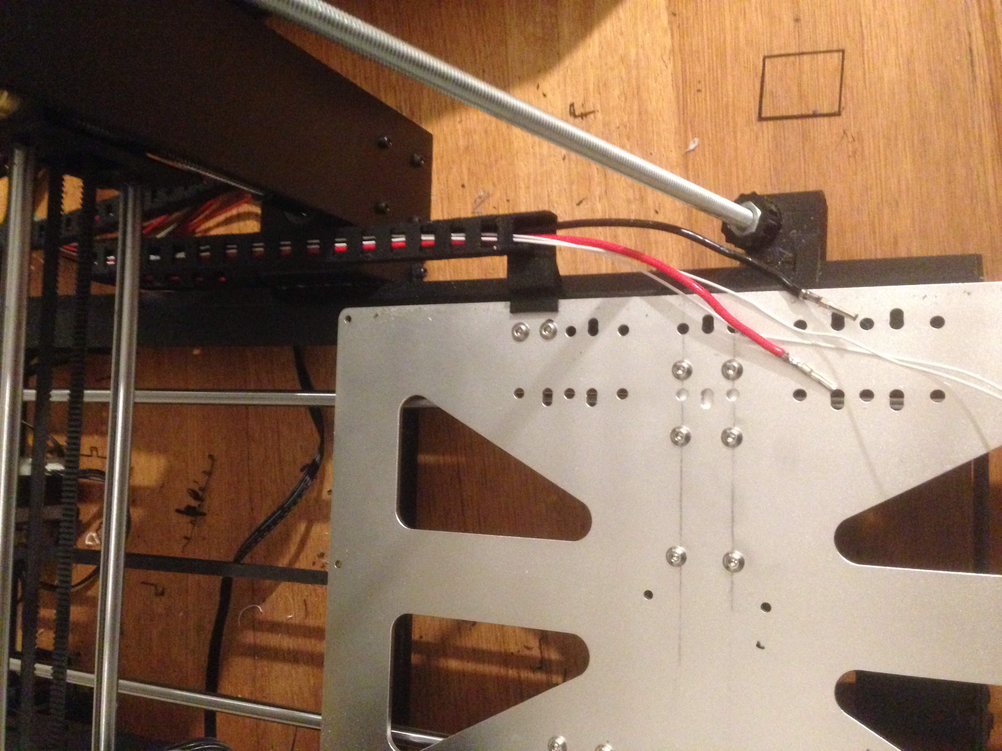

REMEMBER! when printing the cable links make sure that you get your orientation right, you want the lobes at the end of the chains to face upward, otherwise the chain will overextend back onto itself!
As always here are the STL files
Have fun!