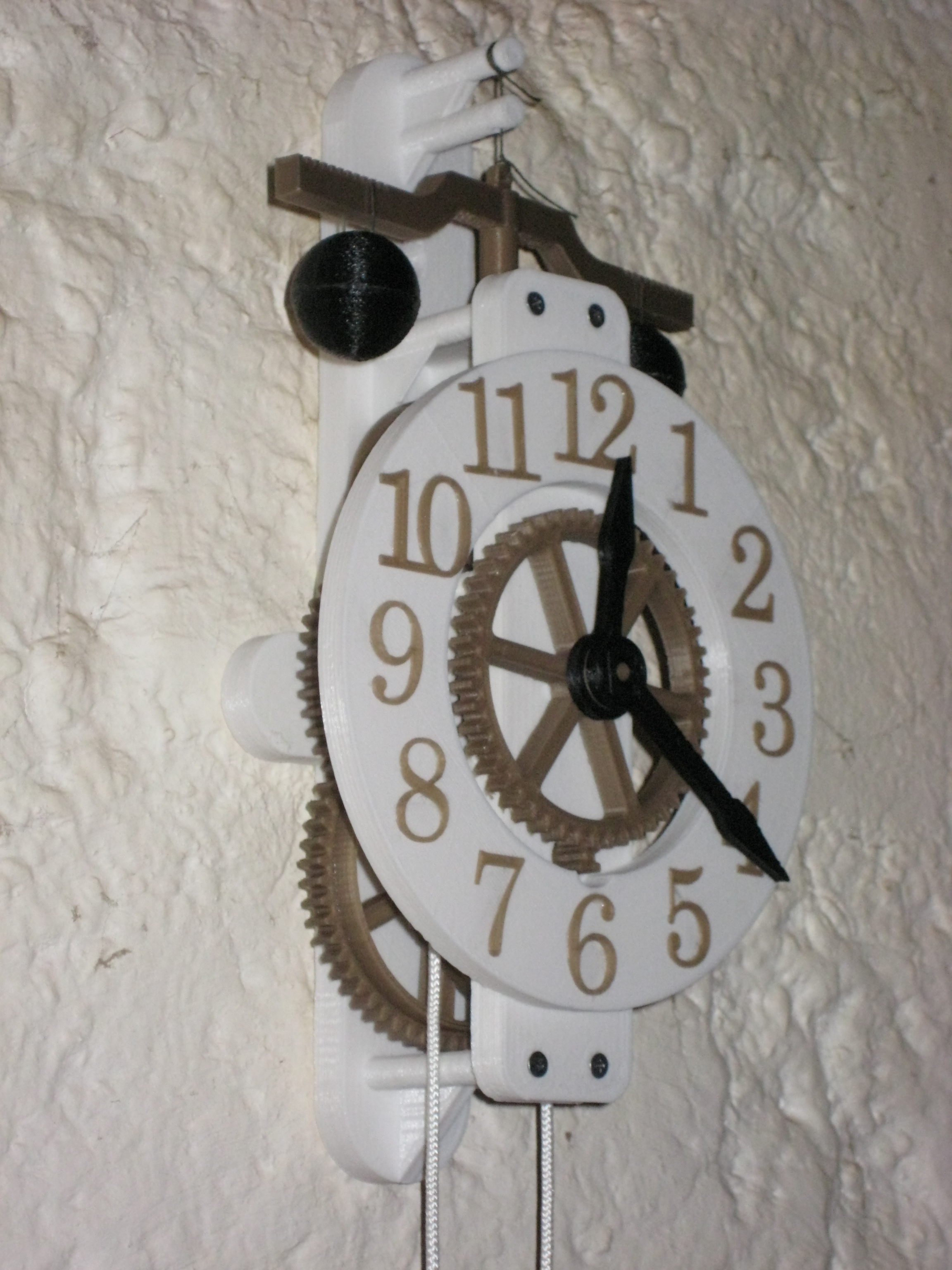
This mechanical weight clock has been designed with ease of printing and construction in mind. The design uses a minimum of specialized parts, requiring just 2x paper clips, 4x 12mm countersunk head timber screws, some epoxy glue, 4x M20 stuctural nuts and 9x M14 nuts. All other parts are printed.
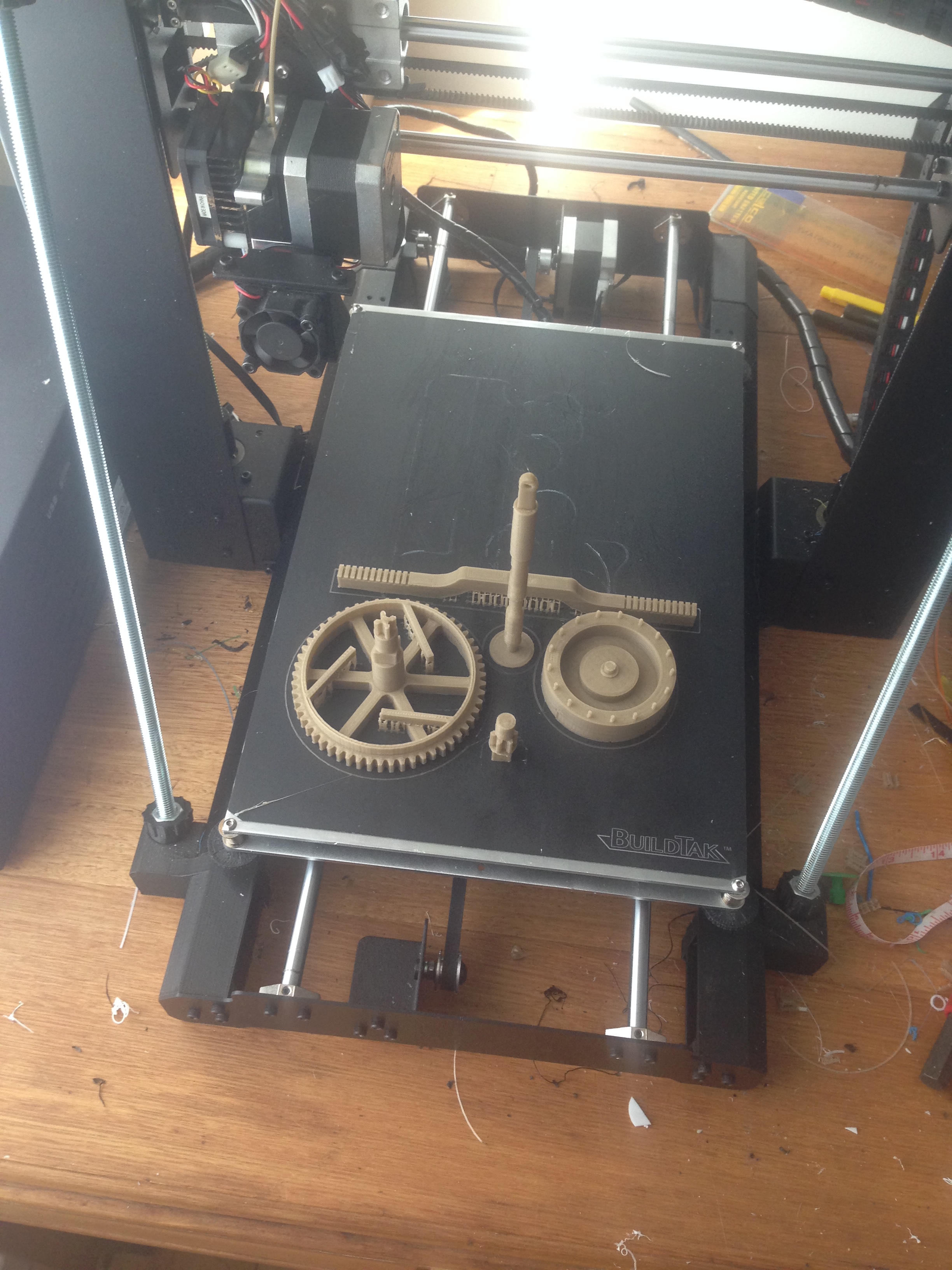
All the gear and mechanical components can be printed on the same platter with supports turned on and about 25% infill.
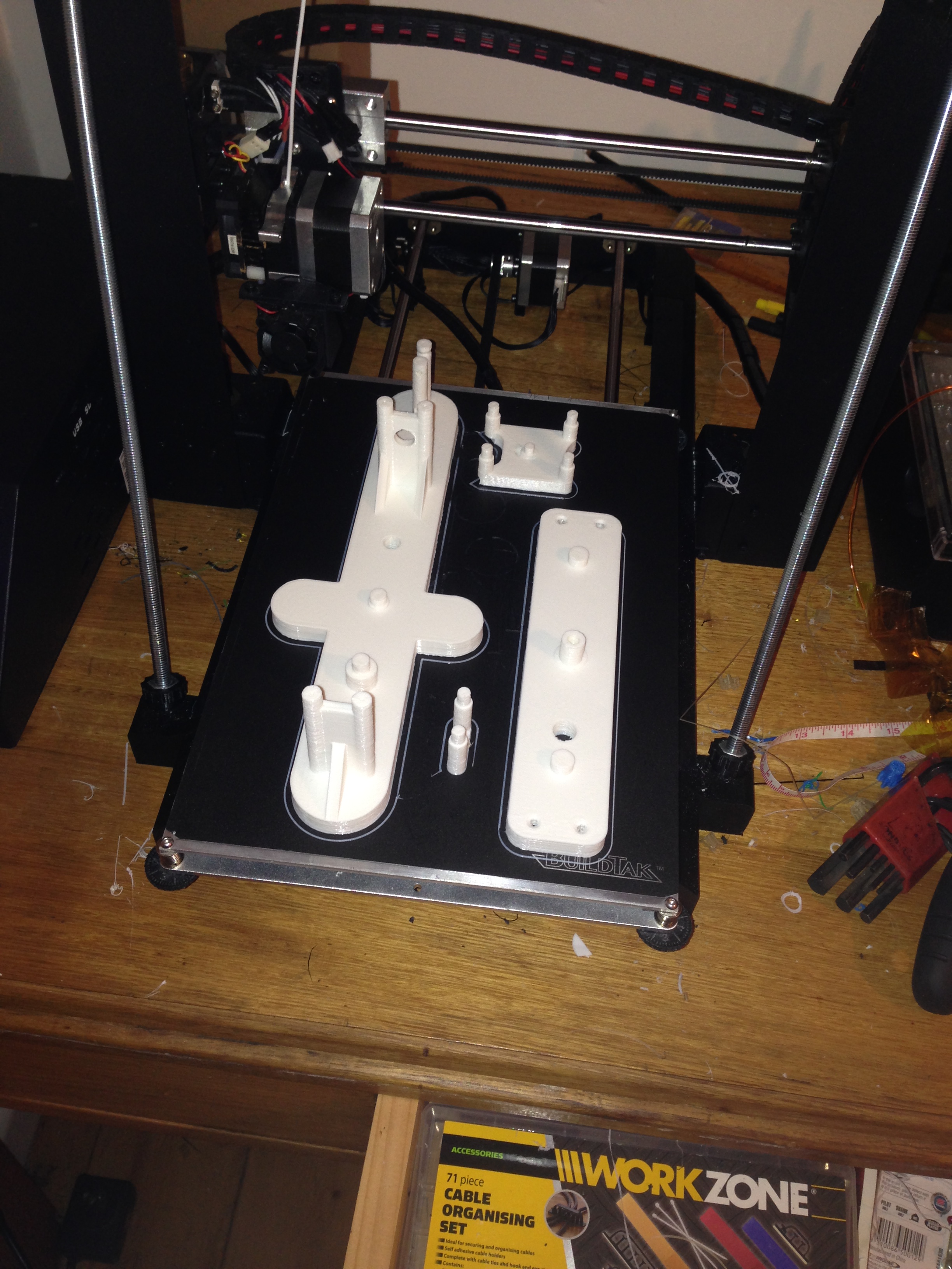
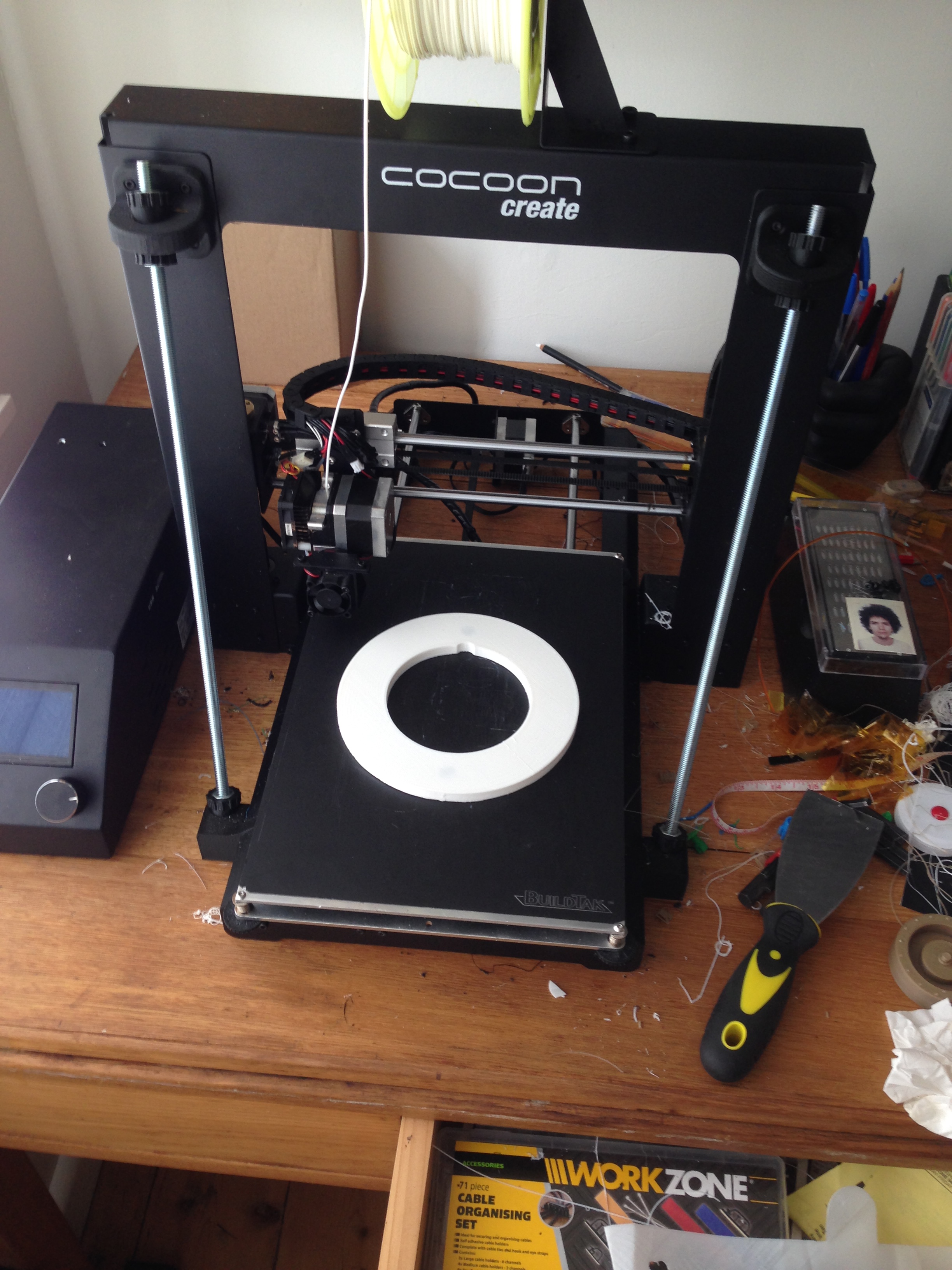
The chassis components can be printed without supports and should for aesthetic reasons be printed in a complimentary colour to the gears. If your printer is not long enough to print the back chassis panel, it can simply be printed in two parts and glued together.

Once the mechanical and chassis components have finished printing it is important to remove the burrs from the gear teeth and bearing surfaces. The easiest way to do this is with a nail file or jewelers file, making sure to clean every tooth on every gear.
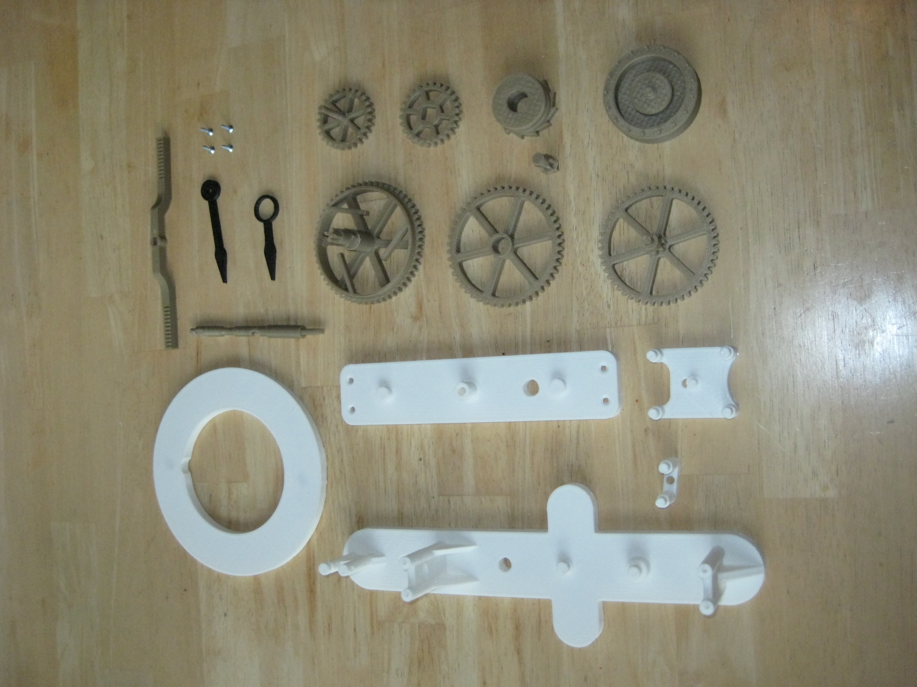
Construction starts by assembling the main shaft. The main shaft consists of a 56 tooth gear, three ratchet arms and a 4 toothed gear at the very end. The cord pulley with its ratcheting teeth fits over this shaft and is kept in position by the 26 tooth minute drive gear which slides over the square collar on the main shaft. The raised collar on the minute drive gear should face outward.
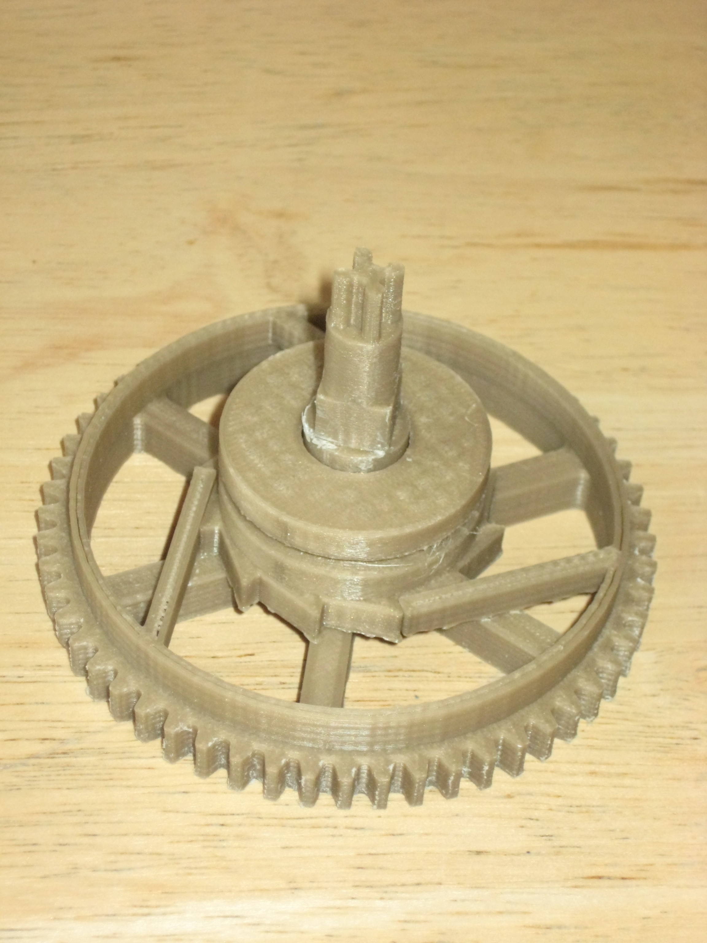
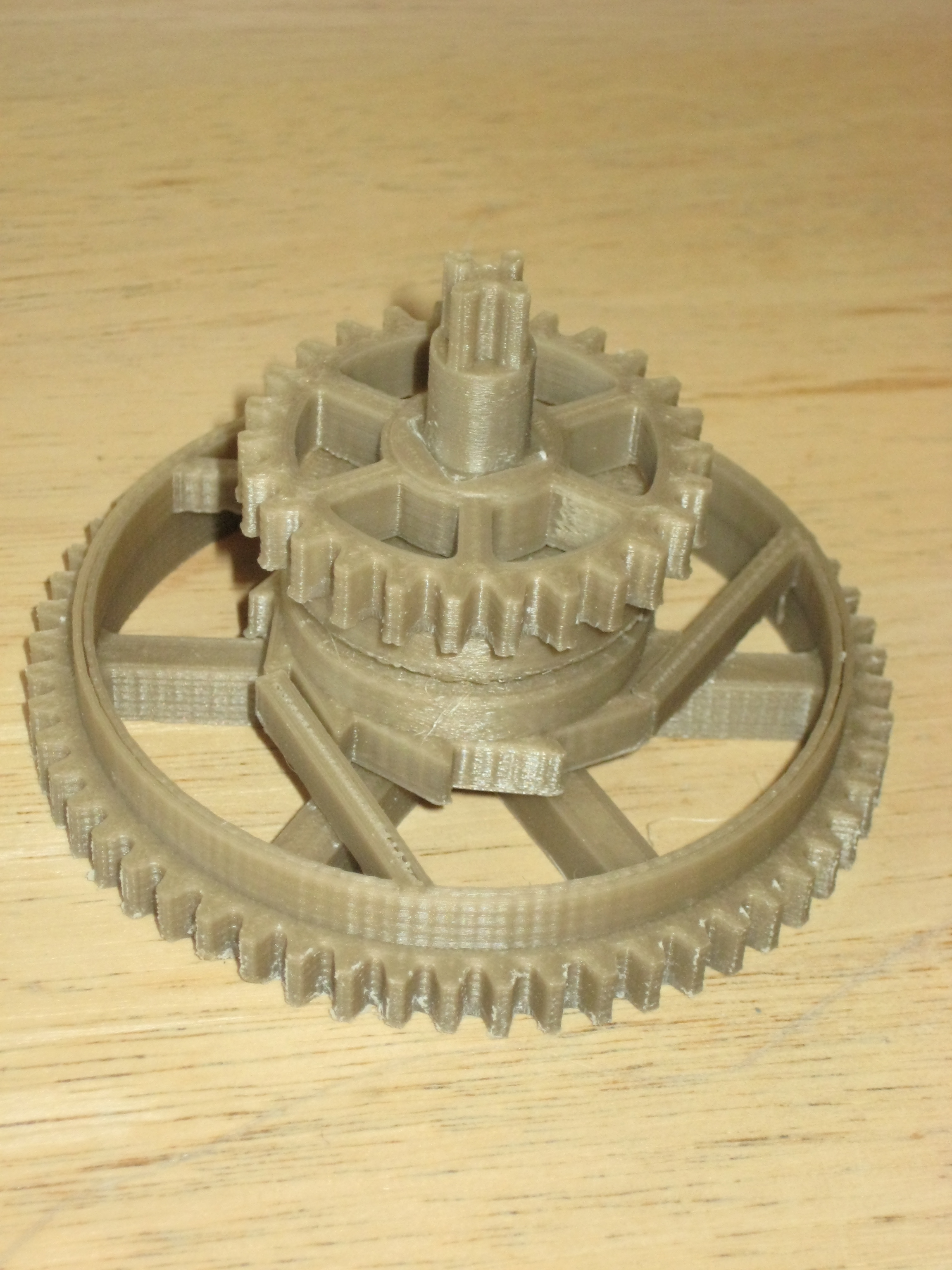
The next part to construct is the escapement mechanism. The escapement wheel has 17 lugs and is driven by an 26 toothed gear. To assemble, this press the square end of the escapement shaft into the square cutaway in the escapement wheel, be careful not to break any of the escapement teeth in this process.
The escapement contacts the cams on the escapement shaft which then drives the two horizontal pendulums from side to side. It is the duration of the pendulums to move from side to side that sets the time taken for the escapement to advance one tooth.
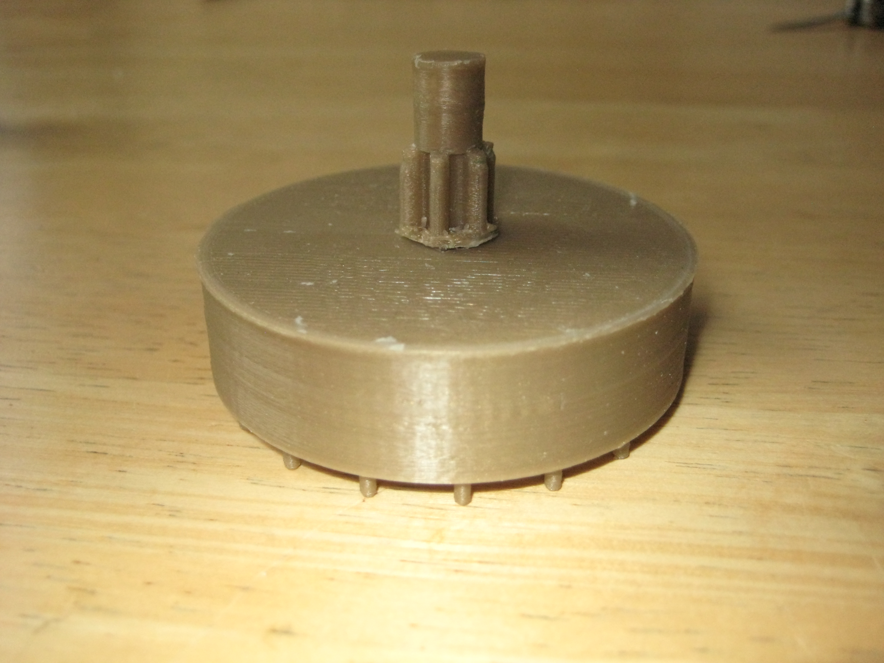
The next step is hour hand onto the hour gear, it might be necessary to file the inside of the hand a little in order to make it all fit nicely.

To begin assembly of the main clock start by fitting the minute hand gear through the hole in the front chassis plate and securing it in place with the minute gear carrier. be sure to fit the carrier the right way up as the escapement shaft rides in the hole at the top.
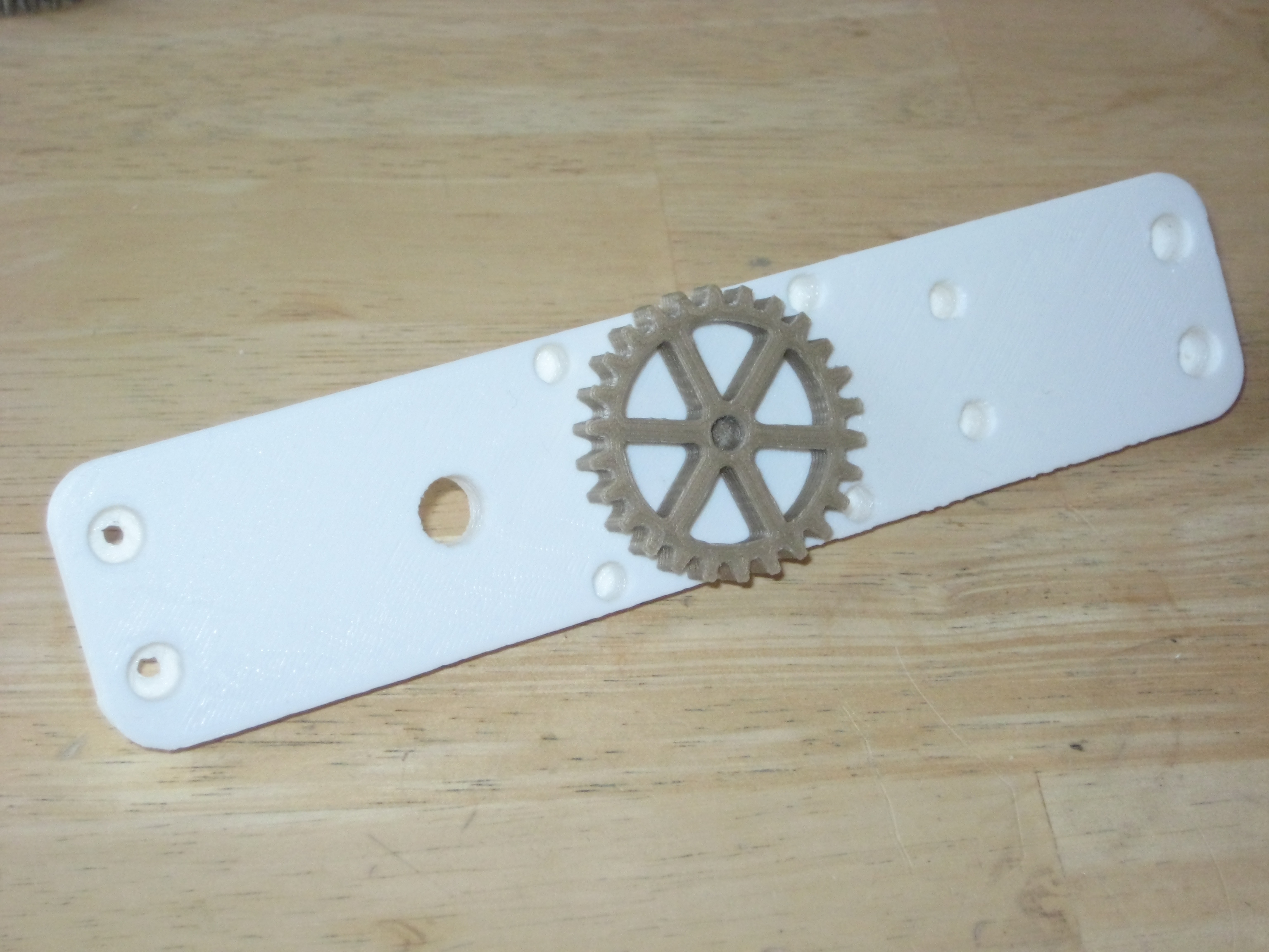
At this stage secure the escapement carrier, if this does not fit in tightly, a little glue can be used to secure it.
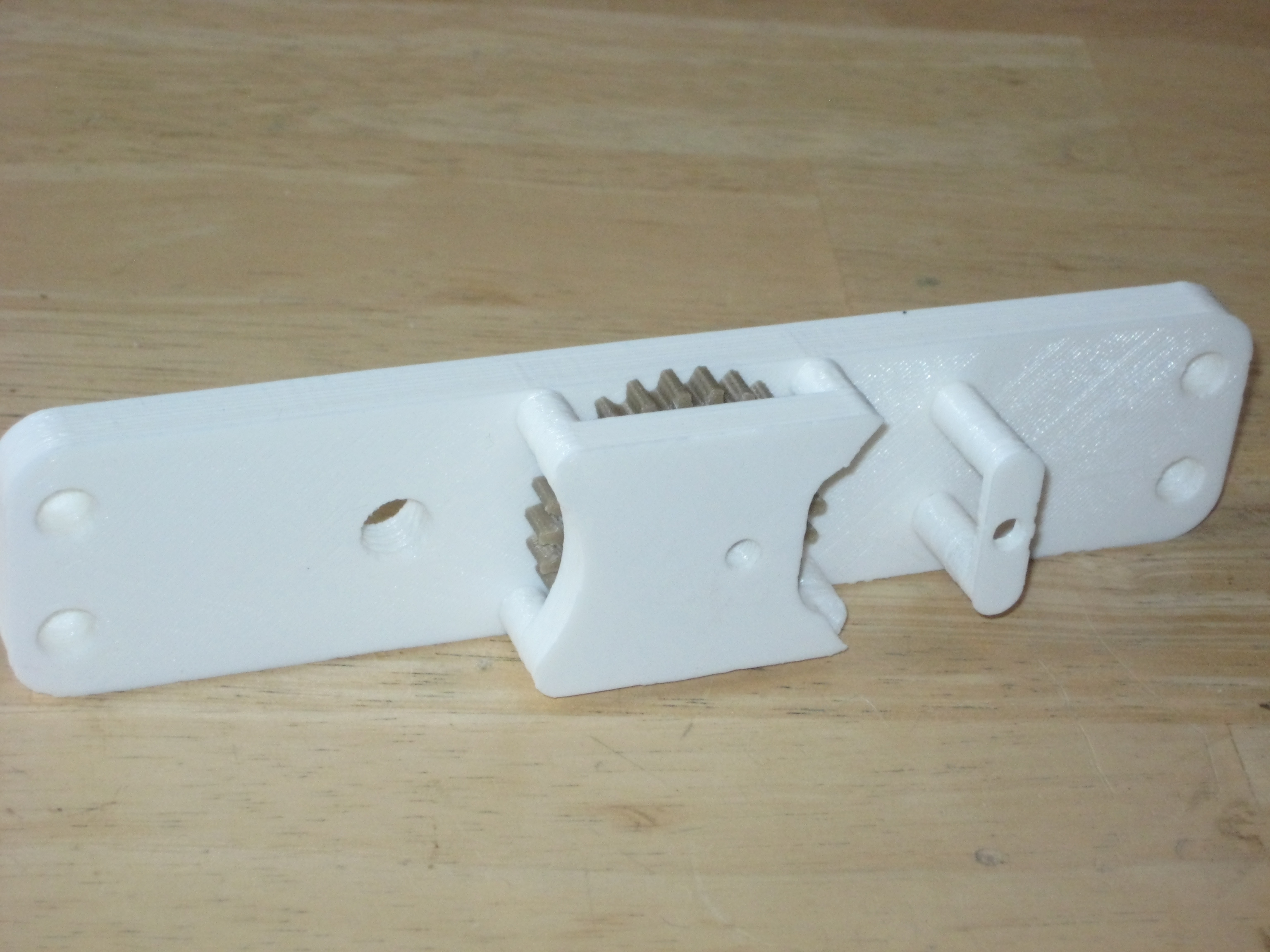
Mount the face plate onto the chassis, then fit the hour gear with hand over the bearing collar.
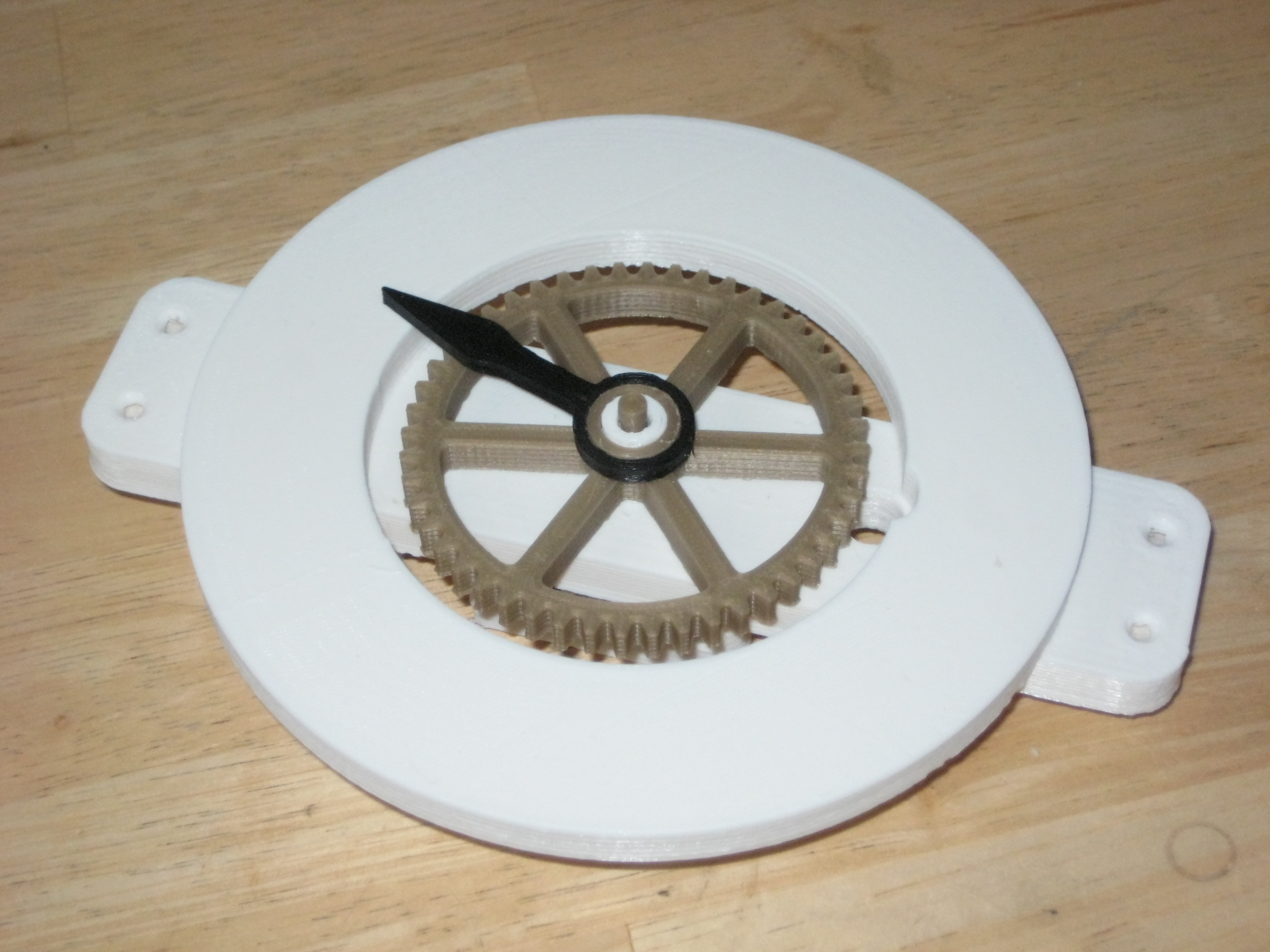
This is a good opportunity to mount the minute hand, as it is easier to apply downward pressure on the shaft in this position.

The next part to assemble into the chassis is the idler shaft. This is a single piece comprised of a 48 tooth gear on one end and 7 teeth on the other. The idler shaft runs off the 56 toothed gear on the main shaft and in turn drives the escapement wheel which is connected to the 48 toothed gear.
Once the idler shaft is fitted into the chassis the main shaft and escapement gear can be mounted onto/into their bearing points.
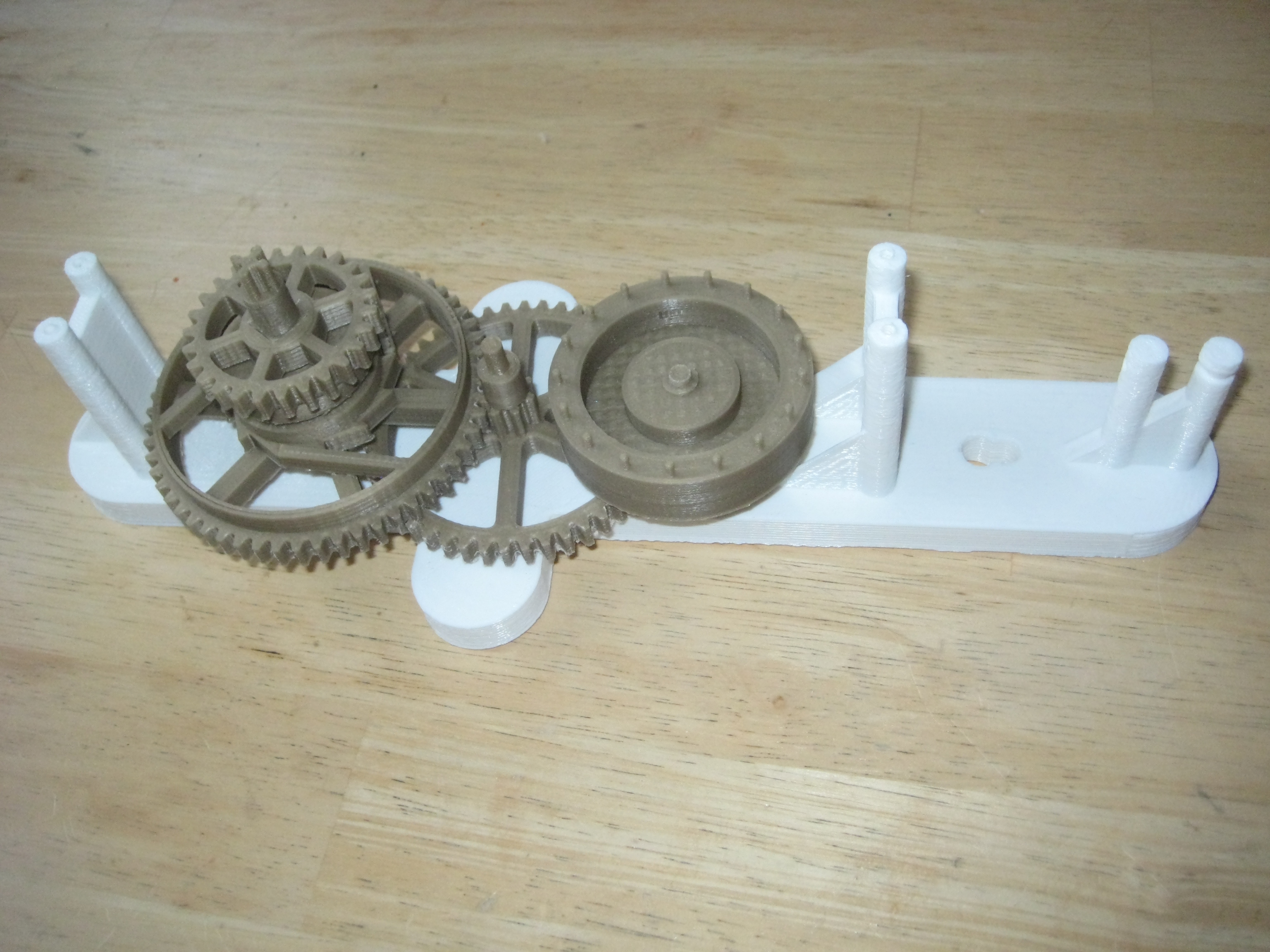
Mount the top of the chassis onto the chassis back taking care to align all the bearing surfaces. Everything should fit snugly with very little force. Once everything is mounted make sure that everything spins freely, if there is any tightness in the mechanism find which part is the culprit and file/sand it smooth.
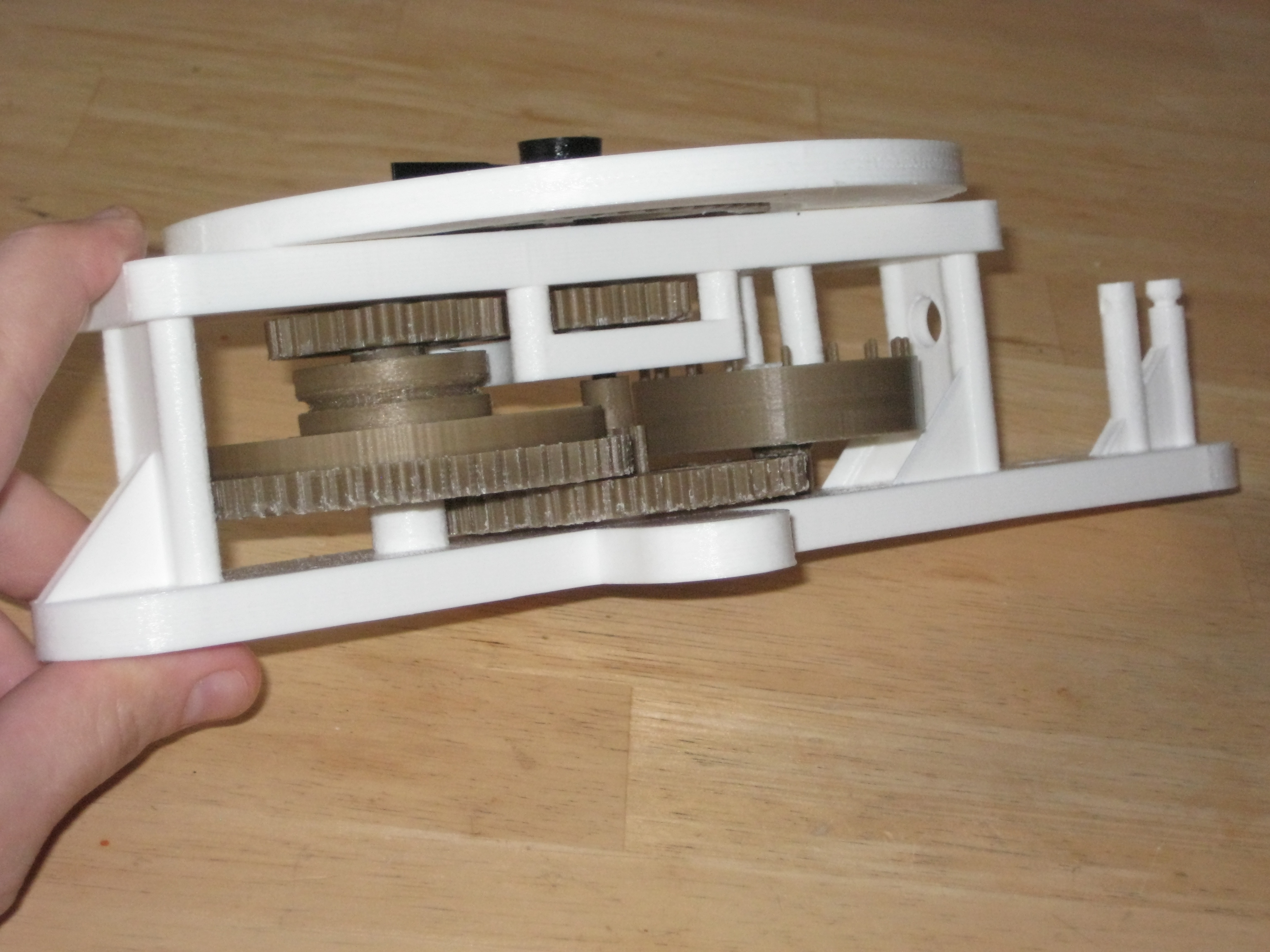
Once everything runs freely screw the front down using four 12mm countersunk head timber screws.
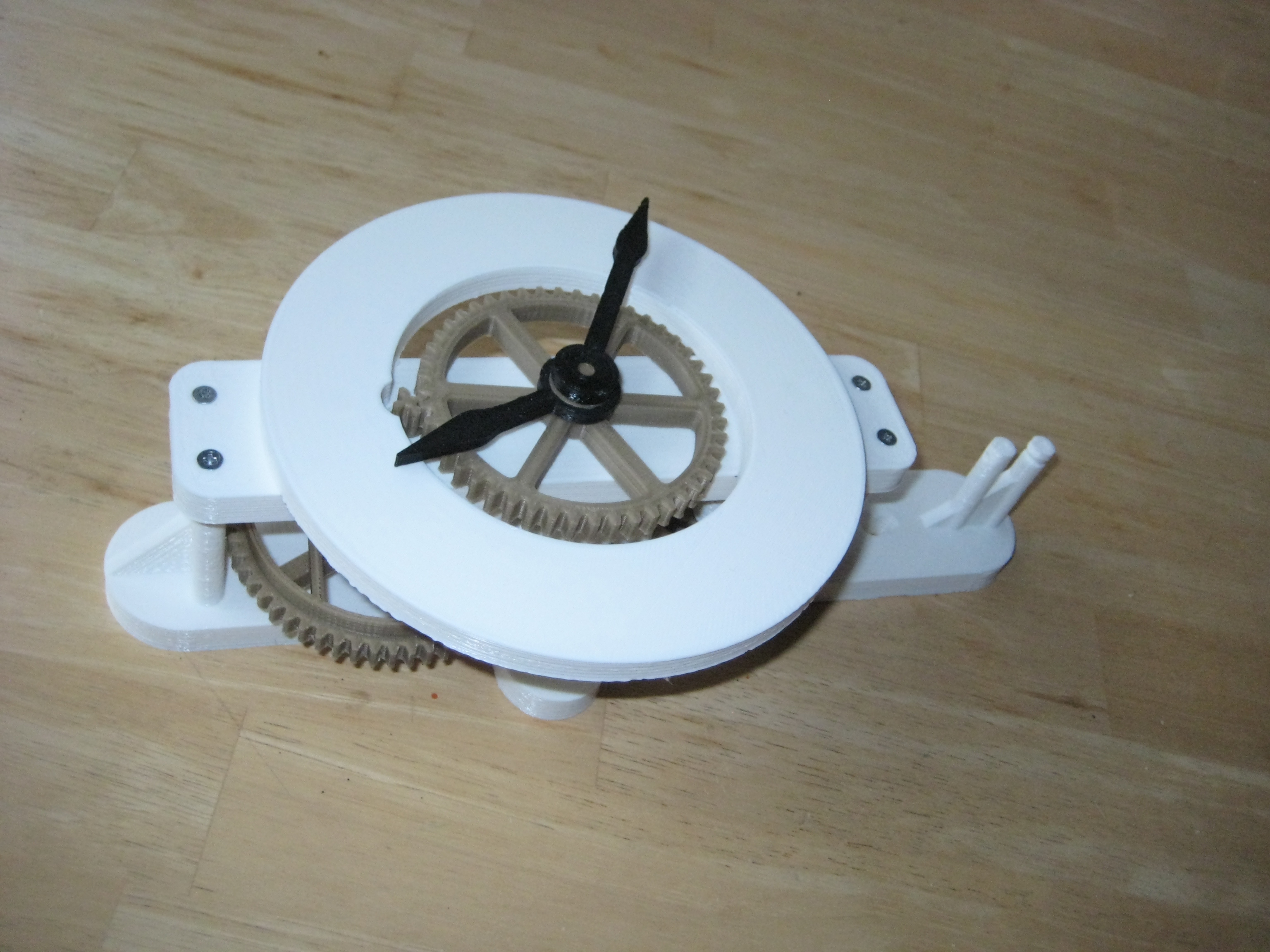
Fit the escapement shaft, this slides in on an angle making sure not to damage any of the teeth on the escapement wheel.
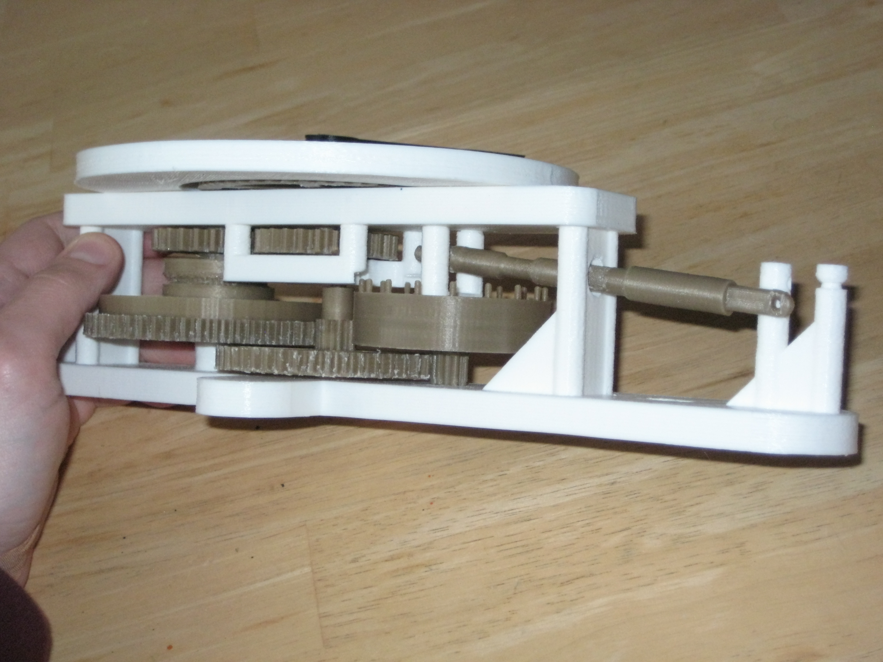
Once the escapement shaft is fitted add the pendulum arm.
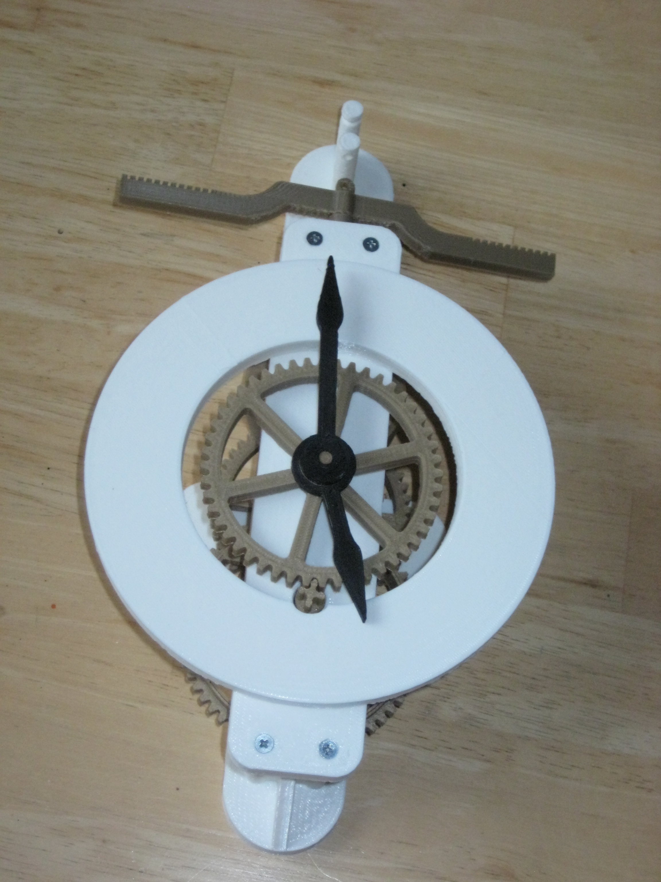
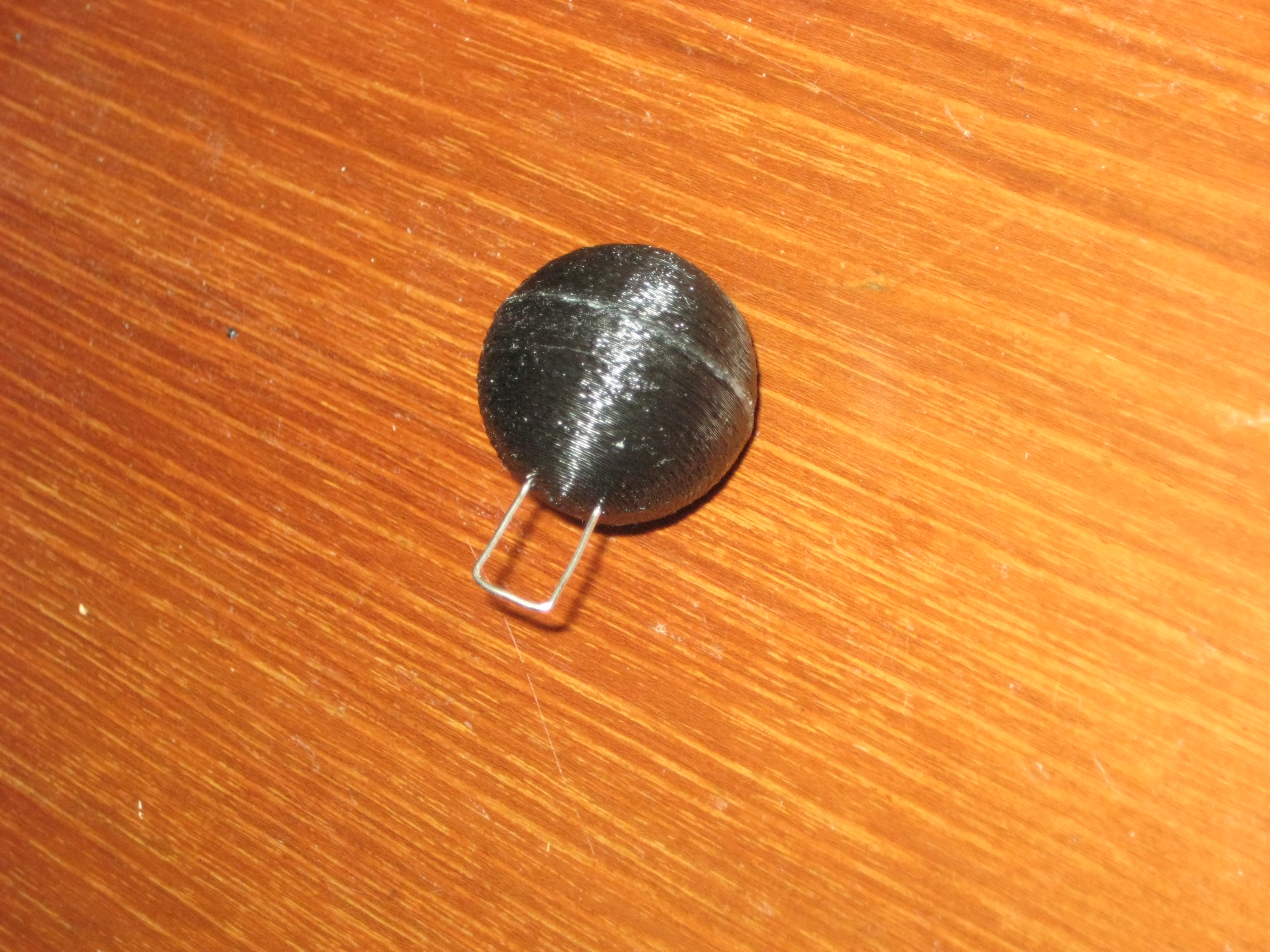
Now that the clock body is assembled it’s time to build the pendulums. The two pendulums consist of two half hemispheres glued together with an M14 nut inside and paperclip loops. These should be printed with supports.
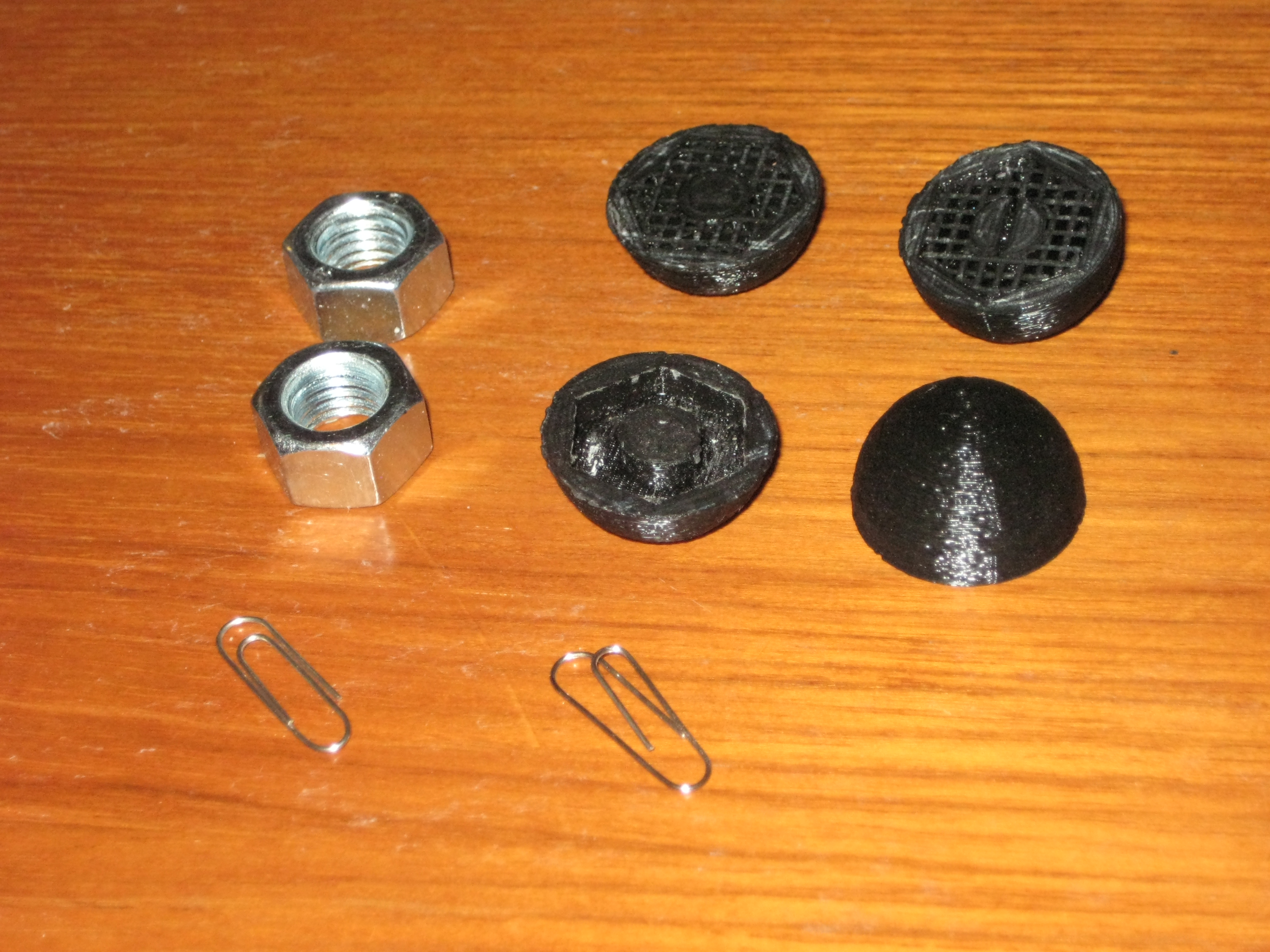
Once the supports have been cut away, unfold and cut two paperclips off at 30mm.
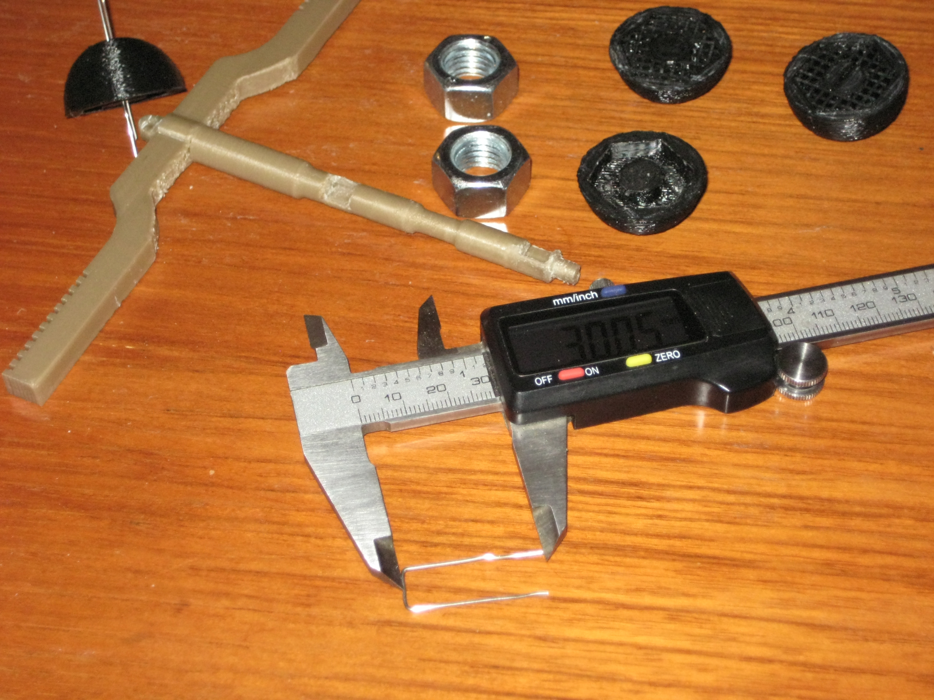
Fit the paperclip loop through the two holes in the top of the pendulum housing and bend the ends over.
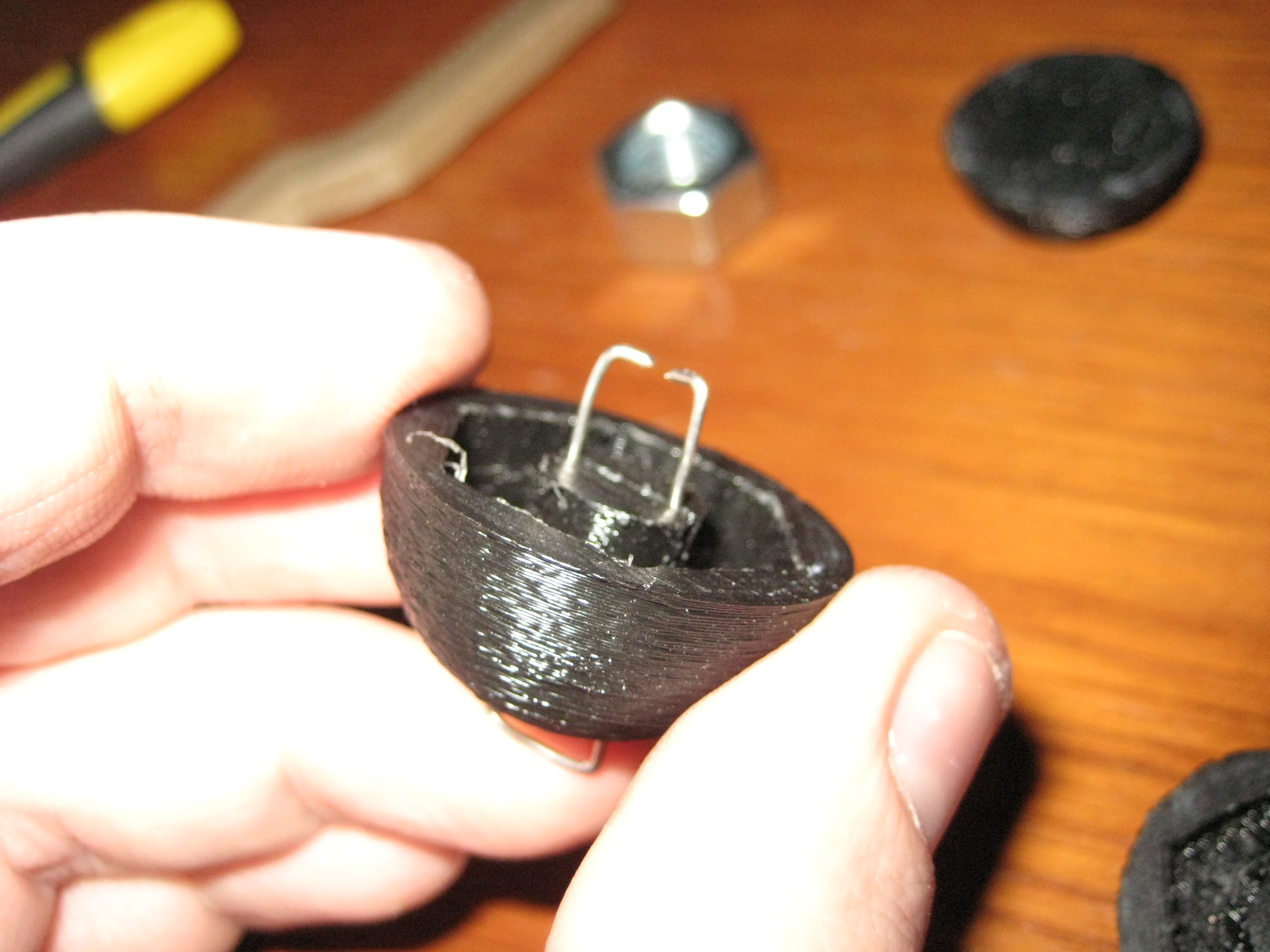
Push the bent over ends of the paperclips into the grove, splash some epoxy around and glue both haves of the pendulum over the M14 nut.
 Building the counterweight is straightforward, simply scale the STL file to fit your nut diameter, then add 7 M14 nuts and glue the lid on.
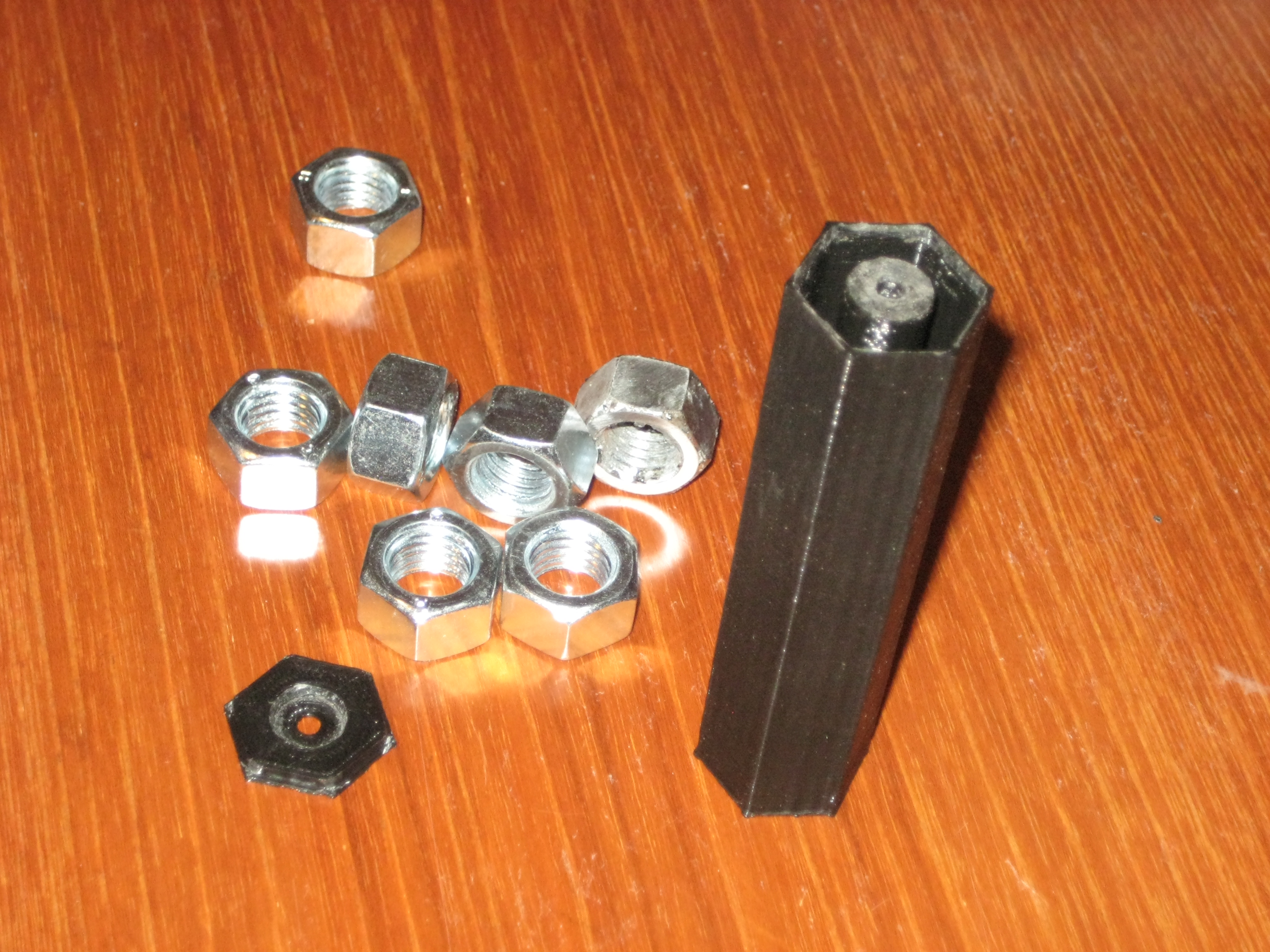
Building the main weight is the same process, simply scale the STL file to fit your nut diameters, add the nuts and epoxy the lid on.

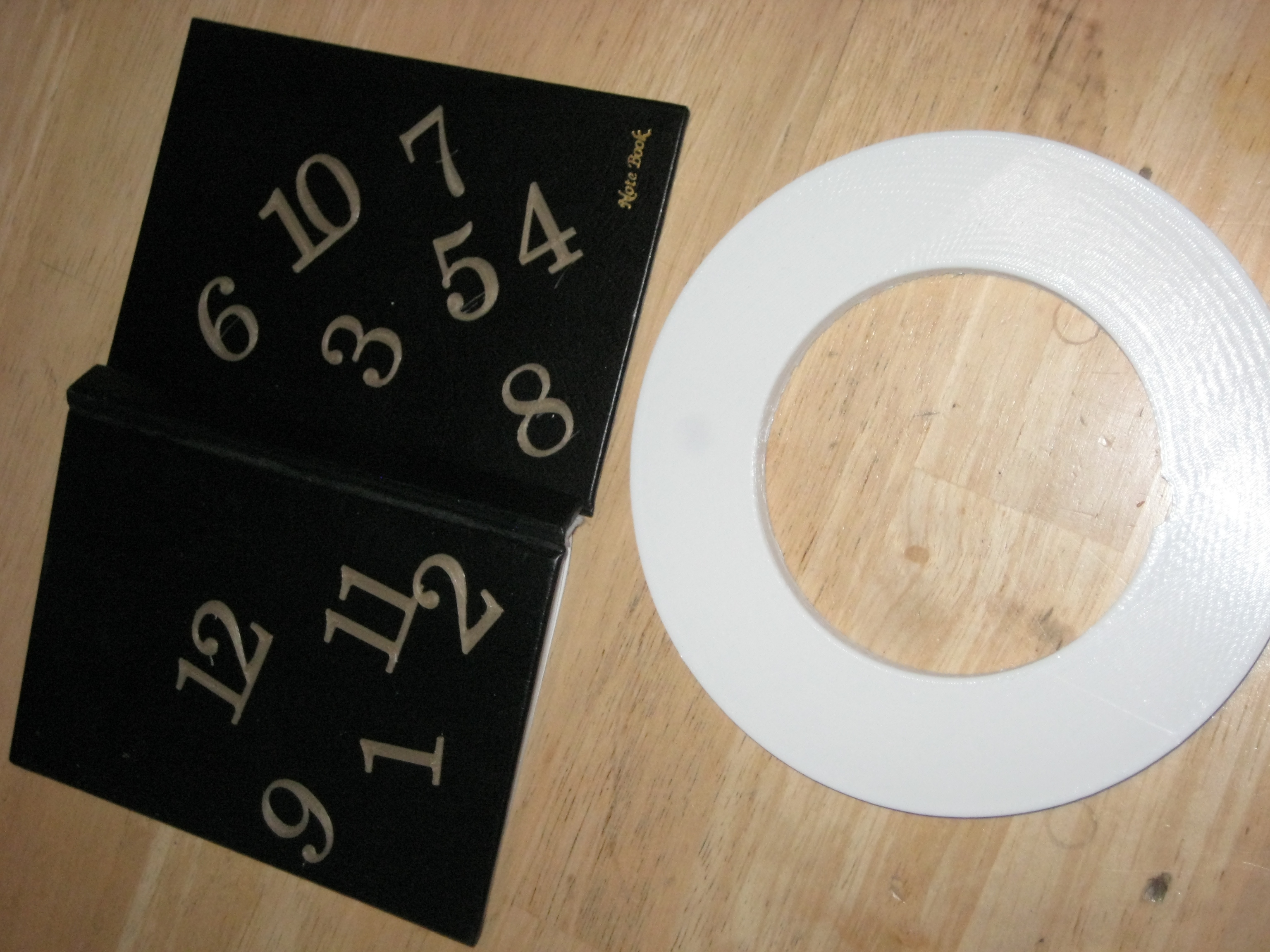
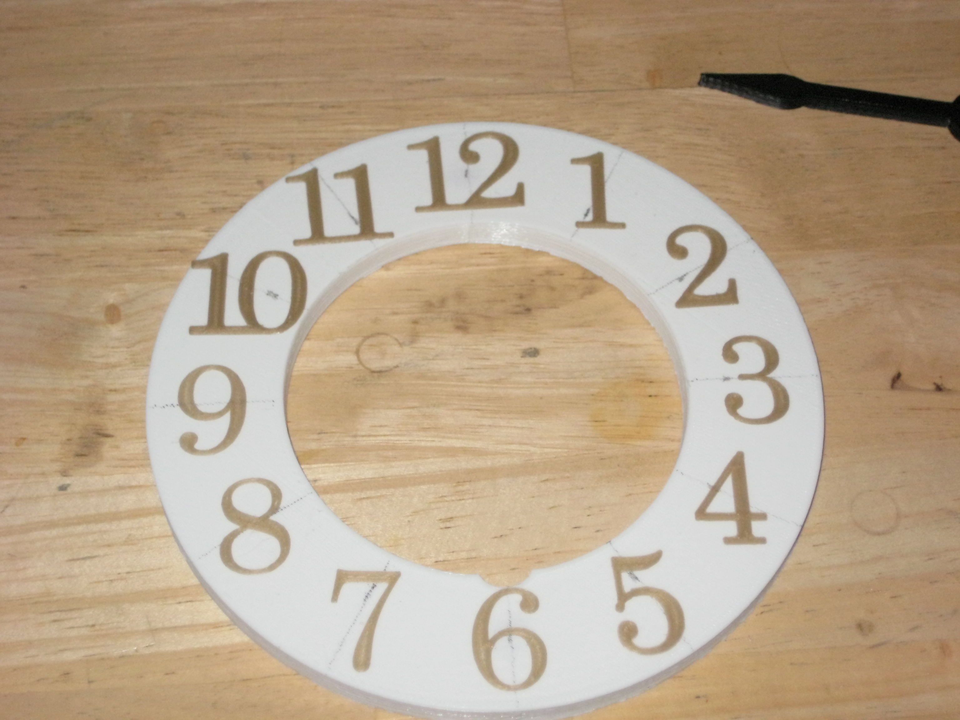
Before finalizing the clock decided that the clock face looked a little bare, so I printed out some numbers 0.3mm in thickness and stuck to the face. You can design your own using any typeface you like be they numbers or roman numerals, you could even write your numbers on by hand with a marker.
The clock is completed by refitting the face, attaching the pendulums to the pendulum arm and mounting the weights and counterweights using a piece of standard blind cord. The escapement shaft should be suspended by a length of cotton so as to reduce any points of friction.
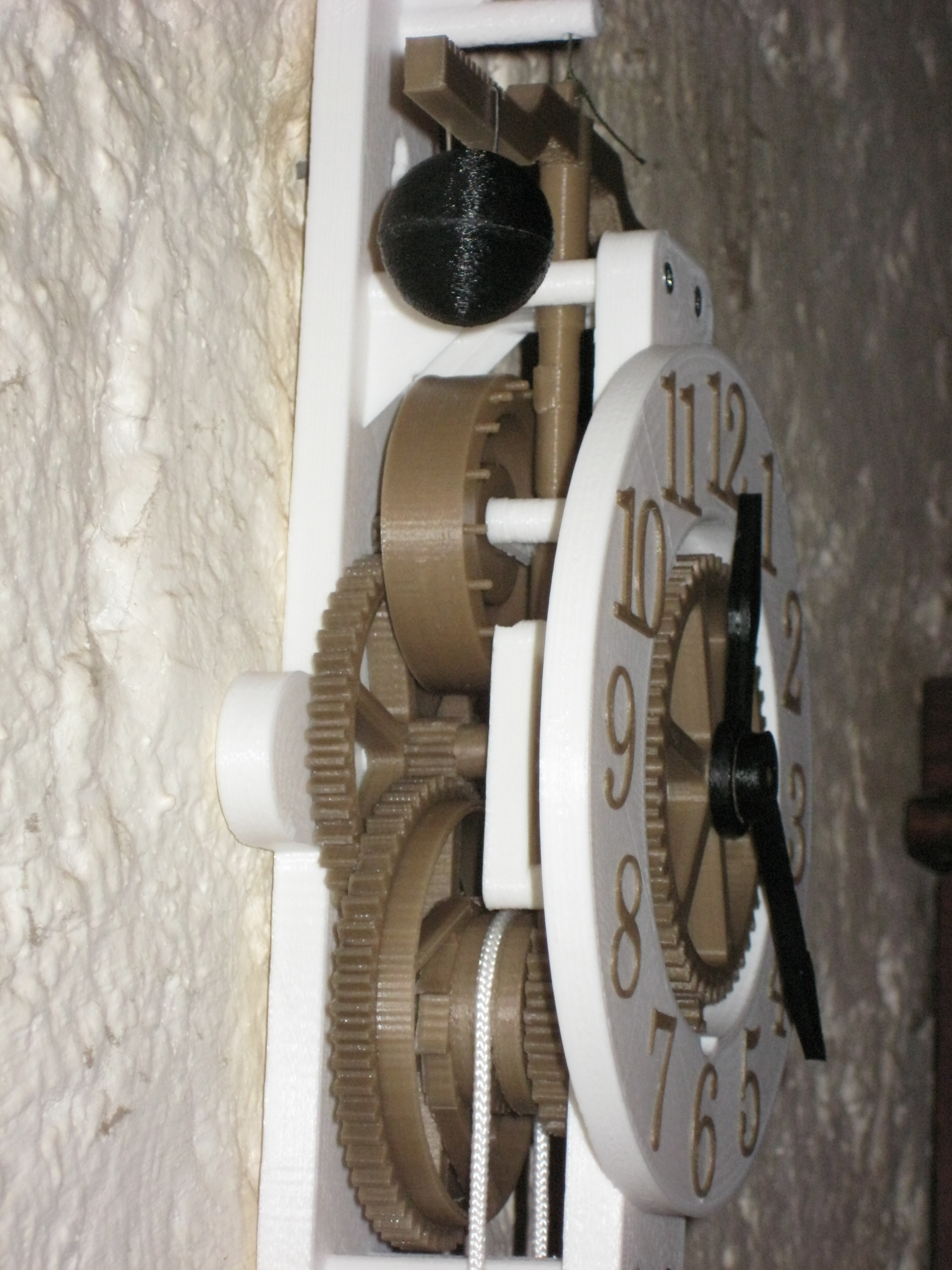
The main weight should sit to the left, with the counterweight to the right. To rewind the clock simply pull the counterweight down, the ratchet will prevent the clock mechanism from running backward or being damaged.
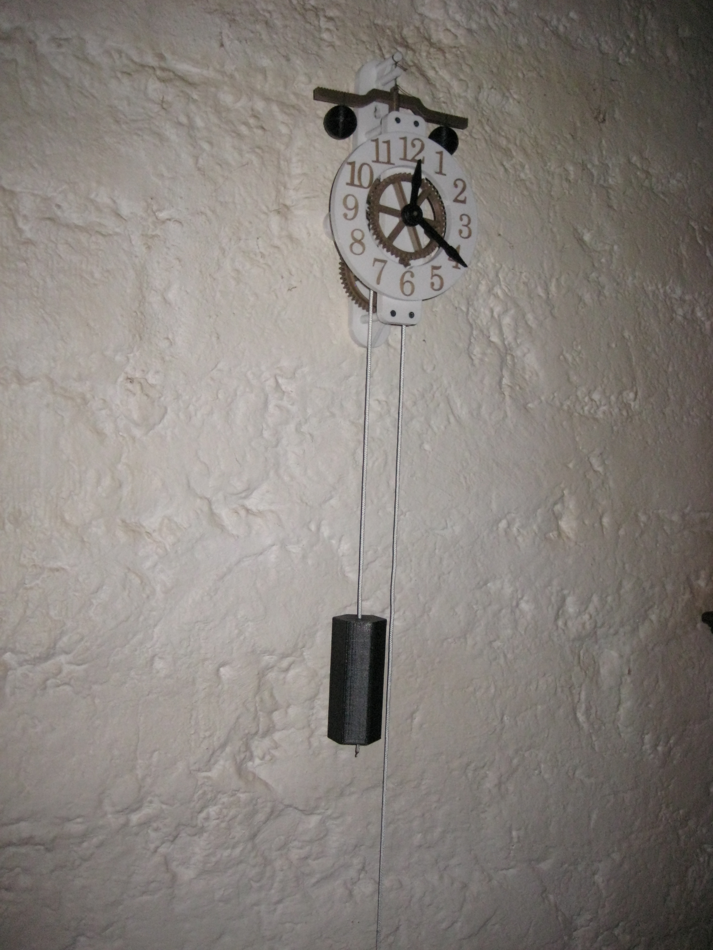
To calibrate the time simply move the pendulum weights along the arm until you find a position that keeps reasonable time. Obviously this won’t keep perfect time, but with proper calibration it can come close.
And as always here are the STL files
There are a few added files to give you more options, for instance there is a file where there are holes in the tack wheel instead of pins, this will allow you to use lengths of filament or nail shafts instead of relying on the strength of the printed pins.
Hello, I am new to 3D printing and my friend asked me if I could print a clock for him. He forwarded me your link. I started to print your plans this weekend and noticed a few missing parts. It looks like these are missing
1) Bottom part of pendulum arm (vertical part)
2) Two bottom pieces of the escapement (Gear with inner racket arms and next piece up Gear with rackets on O.D.)
3) Minute hand (only the tip in the Stl files)
Ah, something must have gone wrong while I was zipping up the latest version of the file, you can quickly find the parts at my thingiverse by looking for retrofluffyboy.
https://www.thingiverse.com/retrofluffyboy/about
Hey, I was wondering how you figured out/designed the gear train. I’ve been trying to make one of my own, and getting the gears to mesh and figure out how to make it work like a functional clock has been maddening to say the least. Thanks for any help!
This was actually my very first 3D design, so it was quite crude with both the software used and my approach, I used 123D Design and the gear template generator from woodgears.ca. I used the gear template generator for all of the gear train components and even the escape wheel as the generator allowed for spoke type gear wheels. The great thing about the gear template generator is that it constructs the gears based on how many teeth you want on each side and whichever shaft spacing you need, so I based the whole thing around the shaft spacing which is super handy when you are stacking gear clusters. I played around a lot to make the gear sizes look ascetically pleasing and also be coarse enough in pitch to be 3D printed on medium/low quality settings.
I finished the initial design with everything meshing tightly with no tolerance… then scaled the gears back around their center shaft till I had about 0.2mm tolerance between the teeth, however this is entirely dependent on printing quality and intuition.
If I were making this today I’d probably use a parametric gear generator as there are so many good ones out there, and design the thing in SketchUp or Solid Works, but I was just starting out.